-
iestinstrument
Battery Storage Gassing Testing Has Never Been Easier!
1. Introduction
Gas generation is an unavoidable phenomenon during the battery manufacturing process and its usage, occurring in various stages such as formation, cycling, overcharging, over-discharging, and storage. Different working conditions require different levels of gas generation and different gas components. Battery storage gassing generation testing is particularly important as it simulates the stability of the battery cells during storage, helping researchers optimize materials and cell design.
With the rapid development of high-capacity silicon-based anode materials, technologies such as surface modification and element doping can significantly increase energy density. However, if there is residual alkalinity or incomplete coating on the surface, reactions with solvents during the slurry mixing process can produce gas, affecting the quality of electrode coating. Therefore, silicon-based anode materials also require evaluation of their gas generation performance in solvents.
2. Traditional Gas Generation Testing Methods
The traditional method of testing battery storage gassing generation typically involves storing the cell in an oven for a set period and then manually removing the cell for single-point volume measurement using a self-made balance device, as illustrated in Figure 1. This non-in-situ method alters the real-time environment and state of the cell, leading to the following issues:
- Multiple devices are required to complete the experiment, such as an oven, voltmeter, balance, and full-charge storage supplementary power equipment.
- Temperature changes during the transfer of the cell can affect the gas volume.
- Manual recording and data sorting are required for cell volume measurement, introducing the risk of data transcription errors.

Figure 1. Flowchart of Non-In-Situ Battery Storage Gassing Generation Testing
3. IEST Innovations in Gas Generation Testing
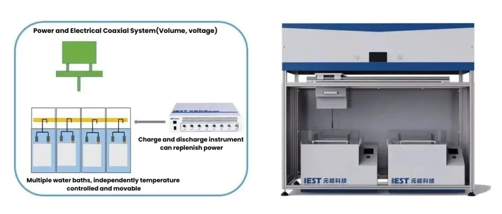
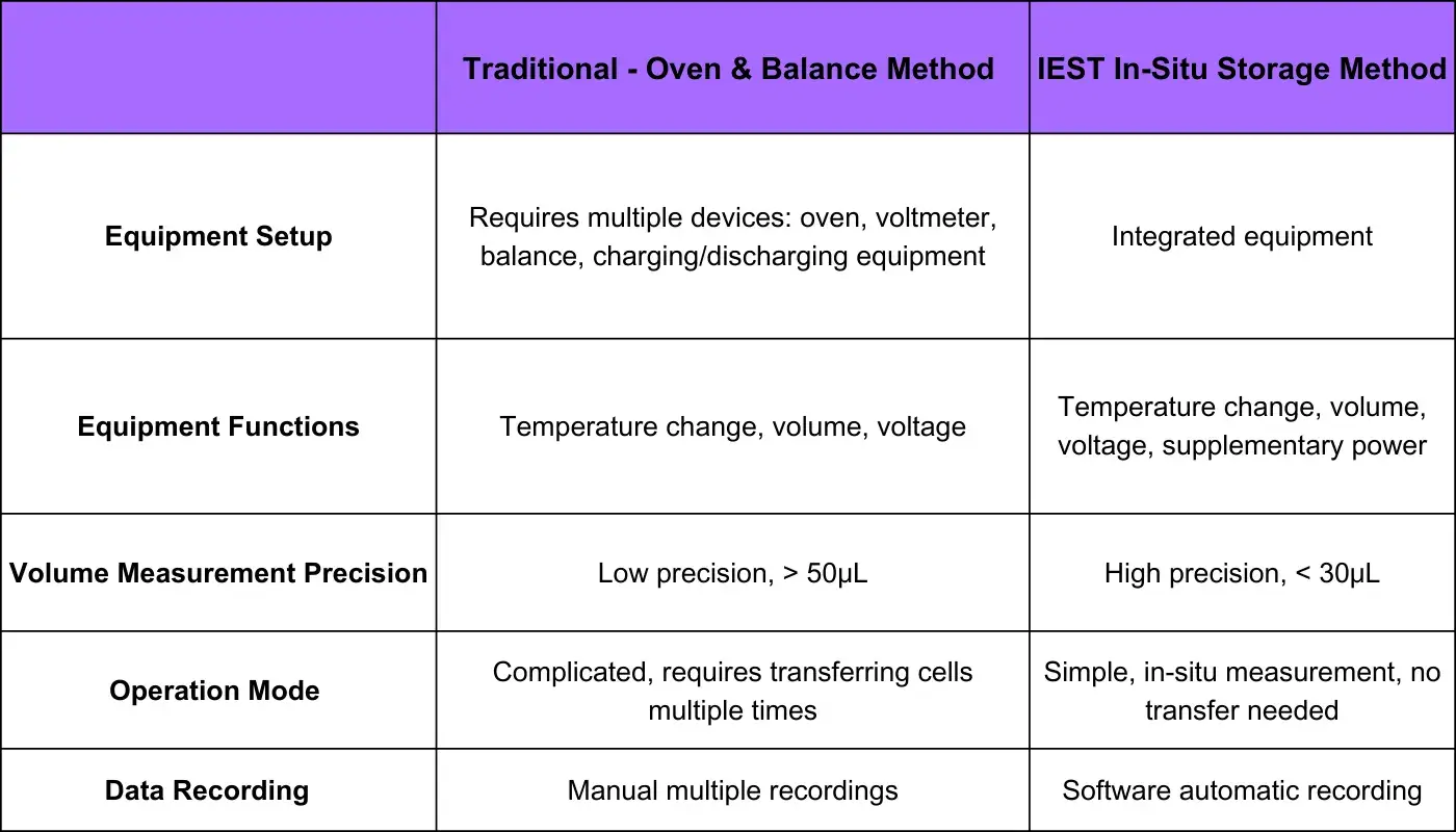
IEST has developed an in-situ multi-channel storage gas generation testing system, as shown in Figure 2, which integrates multi-temperature storage, voltage testing, volume testing, and automatic data recording into a single device. Table 1 compares the functionalities of this new method with traditional methods. The integrated in-situ approach makes storage gas generation testing significantly easier!
Figure 2. Diagram of In-Situ Multi-Channel Storage Gas Generation System
Table 1. Functional Comparison Between Traditional Methods and the MSG2000
4. Principle of Gas Volume Measurement
By combining Newton’s laws (Equation 1) and Archimedes’ buoyancy principle (Equation 2), the specific sensor measures the pull force of the sample in silicon oil in real-time, which is then converted to the cell volume (Equation 3).
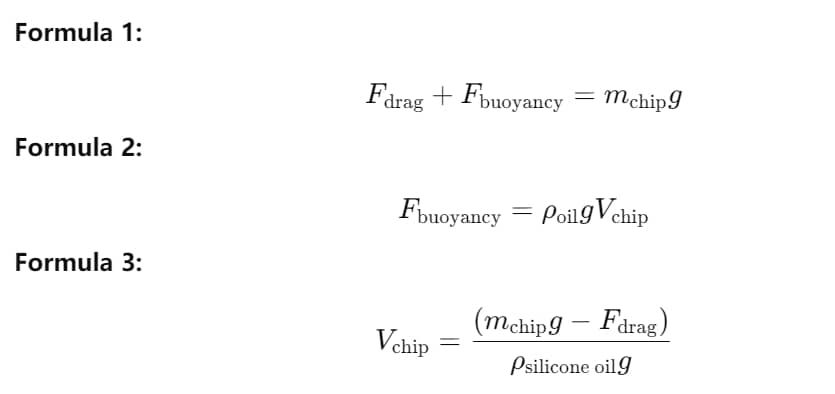
Where gravitational acceleration g is 9.8 m/s², and the density of silicon oil ρ\rhoρ is 0.971 g/ml (at 25°C).
5. Experimental Equipment and Testing Methods
Experimental equipment: MSG2000 (IEST), testing temperature range: room temperature to 100°C, with an optional number of oil baths. The device’s appearance is shown in Figure 3.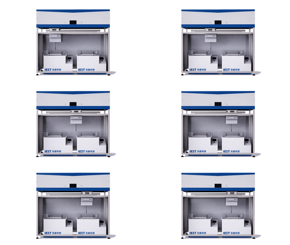
Figure 3. Appearance of the MSG2000 Equipment
6. Battery Storage Gassing Generation Testing Cases
6.1 Ternary Battery Storage Gassing Generation Testing
To further improve the electrochemical performance and storage stability of high-nickel ternary materials, modifications such as doping or coating are typically applied. Figure 4 shows the volume and voltage changes of three parallel samples of ternary cells stored at 70°C for 72 days. After high-temperature storage, the cell volume increased by approximately 13%, and the voltage decreased from 4.35V to 4.1V, indicating that NCM ternary materials experience structural instability at high temperatures, leading to side reactions with the electrolyte and gas generation. Continuous optimization of the high-temperature structural stability of ternary materials is needed.
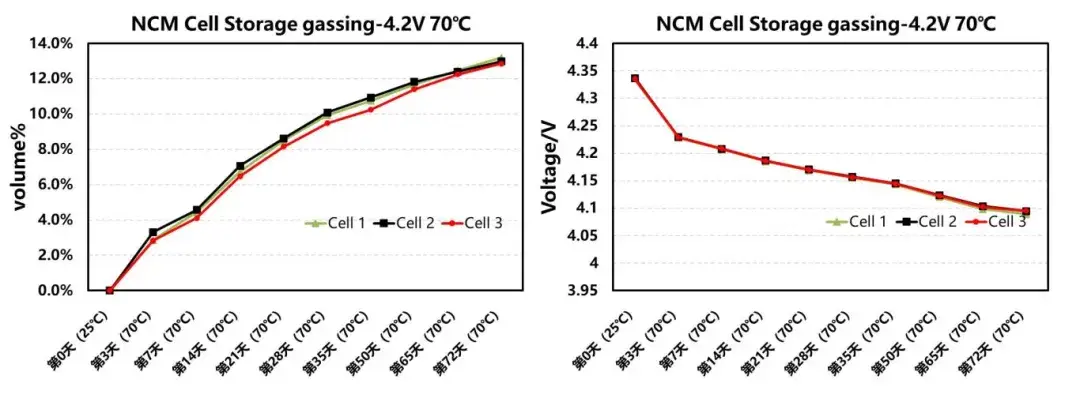
Figure 4. Volume and Voltage Change Curves of Ternary Cells During Storage
6.2 Electrode Gas Generation Testing
Gas generation during battery storage and usage is common, and distinguishing between gas generation from the cathode and anode is crucial for understanding the causes and improving gas generation behavior. Figure 5 shows the gas generation behavior of two fully charged parallel sample cells. After disassembling one cell and separately encapsulating the cathode and anode electrodes with sufficient electrolyte, their gas generation behavior during storage at 65°C was tested. The other cell was directly tested for storage gas generation. The results showed that the gas generation from the anode side was significantly higher than from the cathode side.

Figure 5. Gas Generation in LFP/Gr System at 100% SOC for Electrode Sheets and Cells
6.3 Silicon-Based Slurry Gas Generation Testing
Silicon-based materials have high specific capacity but large volume expansion and low first-cycle efficiency. Surface modification, element doping, and prelithiation are common methods to reduce volume expansion and improve first-cycle efficiency. However, these modifications may introduce instability factors, such as residual alkalinity and incomplete coating, leading to reactions with hydroxide ions and gas generation during slurry preparation, causing issues in the coating process. Figure 6 shows the gas generation over time for silicon-based materials with three different modification processes made into slurry using the same formula. Scheme A had the lowest gas generation, indicating that modification Scheme A is superior to the other two.
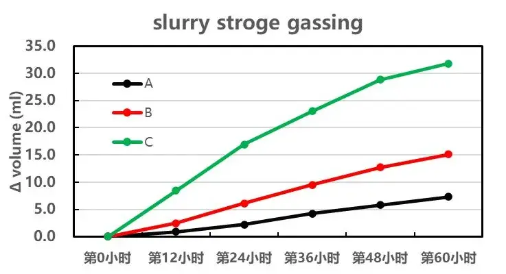
Figure 6. Gas Generation of Silicon-Based Slurry with Different Modification Processes
7. Summary
This study utilized IEST multi-channel storage gas generation system (MSG2000) to test gas generation in silicon-based slurry, electrode sheets, and battery cells, achieving comprehensive gas characterization from the material level to the electrode level and then to the cell level. This system can greatly aid in material and cell development.
Subscribe Us
Contact Us
If you are interested in our products and want to know more details, please leave a message here, we will reply you as soon as we can.


