-
iestinstrument
Systematic Solution For Rapid Testing Separator Ion Conductivity
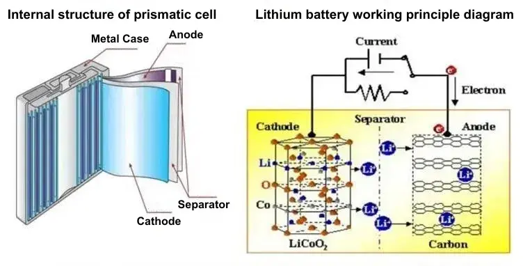
Cathode, anode, electrolyte and separator are the four main materials that make up lithium-ion batteries. During the charging process of a lithium-ion battery, lithium ions are detached from the cathode transported through the separator through the electrolyte, and then embedded in the anode, the discharge process is the opposite. Because the separator plays the role of isolating cathode and anode in the battery, the separator must meet the following points:
- Electrical insulation;
- Easy to be wetted by the electrolyte, and have a certain ability to retain liquid;
- Good mechanical properties and structural stability;
- Good chemical stability to electrolyte, impurities, positive and negative electrode reactants ;
- Can effectively prevent the migration of particles, colloids or soluble matter between the two electrodes;
- Have a certain porosity, separator ion conductivity is good.
In liquid lithium-ion batteries, the existing separator materials are usually PE material, PP material or a mixture of the two (PP, PE, PP/PE/PP). this type of material undergoes certain processes and is stretched to obtain a membrane base material of a certain thickness. This type of membrane must have a high porosity to ensure ion transmission performance. However, because the battery generates a lot of heat during charging and discharging, PP and PE separators will thermally shrink at high temperatures. To improve the heat shrinkage performance of the separator, the separator is usually coated with nano-alumina or boehmite powder [1].
Separator ion conductivity performance is mainly determined by the porosity and tortuosity of the separator. For the detection of separator ionic conductivity transport performance testing, the ion conductivity test method in 6.6.2 of《GB/T 36363-2018: Polyolefin Separators for Lithium-Ion Batteries》is currently commonly used in the industry [2].

Figure 1. Schematic diagram of the internal structure and working principle of the battery
1. Experimental Part
1.1 Test Equipment
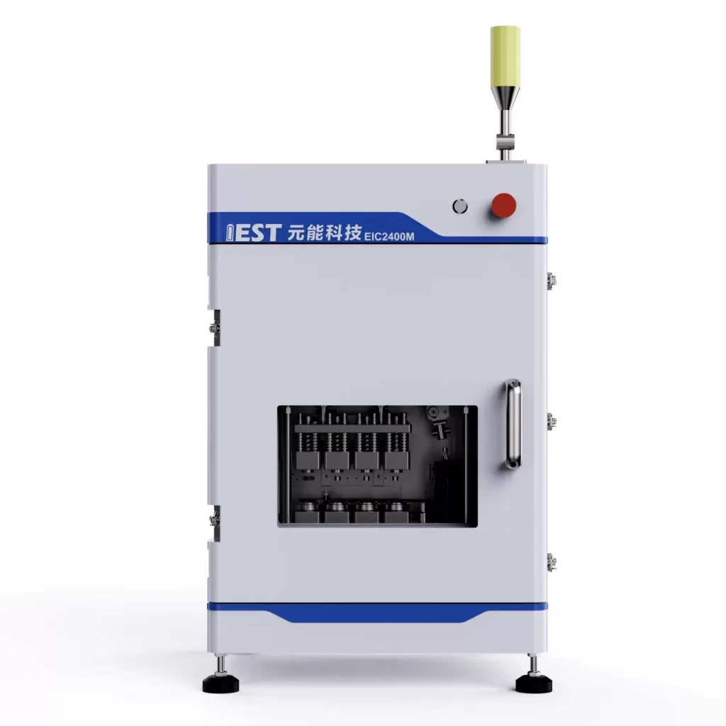
IEST independently developed multi-channel ion conductivity test system is used for testing. As shown in Figure 2. The instrument includes a four-channel symmetrical battery assembly jig, an electrochemical impedance test system, fitting software, etc. It can be combined with high-purity argon or nitrogen to control the inert atmosphere of the test environment to achieve electrochemical impedance spectroscopy testing of multi-channel symmetrical batteries or different separators.
Figure 2. Innovative IEST Electrode Tortuosity Tester & Separator Ion Conductivity Test System(EIC Series)
Figure 3. Appearance of IEST Electrode Tortuosity Tester & Separator Ion Conductivity Test System(EIC Series)
1.2 Test Steps
To verify the consistency of the equipment and the actual test conditions, we used separators treated with different processes and different aging temperatures to conduct ionic conductivity tests. The main experimental procedures are as follows:
- Cut the diaphragm into small diaphragms of a certain area, and bake them in vacuum at 60°C for 12 hours.
- After baking, the diaphragm is assembled in the mold and transferred to the instrument.
- Perform vacuuming-inflating and other steps to remove the relevant air and moisture in the sample.
- Automatically and quantitatively inject liquid (300μL, 1M LiPF6, EMC:EC: DMC=1:1:1) into each channel, and let it sit for a certain period after completing the injection.
- After the rest is completed, the EIS module of the IEST multi-channel separator ion conductivity testing system is used to conduct impedance testing.
- Complete the assembly and testing of 1 to 4 layers of diaphragms respectively, use automatic fitting software, and use the obtained EIS as the baseline for fitting. The intersection point of the impedance and the X-axis is Rs, as shown in Figure 4. By fitting the EIS test results of the n-layer diaphragm, the resistance Rs(n) of the n-layer diaphragm can be obtained.

Figure 4. Diaphragm fitting diagram of separator ion conductivity Rs
The diaphragm is a porous structure with pores filled with electrolyte, and the equivalent circuit of its AC impedance spectrum can be described by a series circuit of a CPE phase element and an ionic resistor, as shown in Figure 5. The impedance of its equivalent circuit is given by the following equation:

Among them, in the corresponding Nyquist plot (Fig. 3), we simply determine the ionic resistance R Ion within the porous separator by high-frequency extrapolation (ω → ∞), that is, the intersection of the impedance spectrum with the real axis Rs.

Figure 5. Equivalent circuit of the electronically insulating porous separator under blocking conditions
2. Result Analysis
2.1 Case 1: Different Separator Treatment Processes
Two separators with the same thickness but different processing techniques are used. The total thickness is 12 μm, named SEPE-1 and SEPE-2 respectively. The test EIS is shown in Figure 6. We can find that there is a big difference between the two EISs, where SEPE-1>SEPE-2.

Figure 6. Diaphragm EIS after different processes
Through fitting calculations, we can obtain the Rs values of SEPE-1 and SEPE-2 under different numbers of layers. The COV of Rs values are all within 5%, indicating good consistency among different parallel samples and stable and reliable test results.
Table 1. Resistance test fitting results for different layer numbers

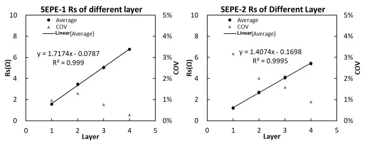
Using the number of layers as the X-axis and Rs as the Y-axis, the relationship between the number of layers and resistance Rs can be obtained, as shown in Figure 7.

Figure 7. Separator Rs after treatment with different processes
According to the national standard formula, it can be calculated that SEPE-1 ionic conductivity is 0.454mS/cm, SEPE-2 ionic conductivity is 0.554mS/cm, the diaphragm SEPE-1 ionic conductivity is smaller than the diaphragm SEPE-2, which indicates that SEPE-2 treatment process is better. The size of the diaphragm ionic conductivity depends on a variety of factors, including the material of the diaphragm, thickness, pore size, porosity and so on. The ceramic coating structure on the surface of the diaphragm will also have an important influence on the ion conductivity, whether it is the surface coating layer or the diaphragm body, the diaphragm with a larger pore size can increase the transmission rate of ions, and the diaphragm with higher porosity can increase the number of ions’ channels, which can increase the ionic conductivity. Different treatment processes result in different diaphragm microstructures and therefore diaphragms with different ionic conductivities.
2.2 Case 2: Aging temperatures of different battery cells
After completing the chemical formation of lithium-ion batteries, they are usually left at a certain temperature for a period of time, so that the battery polarization is fully released at the same time, the cell side reactions are more complete, and the cell interface is more stable. This process is called aging in the cell process. During the aging process, different ambient temperatures and resting time have great influence on the performance of the battery cell. In order to explore the effect of aging temperature on the diaphragm, we will be formed into a battery cell at room temperature and high temperature 60 ℃ static 48h, and then disassembled the battery cell, take the diaphragm for ionic conductivity test.
The diaphragm material is PP, and the thickness of the substrate is 9 μm. In the process, the double-sided ceramic coating process is used, and the thickness of the single-sided coating is 2 μm, i.e., 9+2+2 process. Its EIS test results are shown in Figure 8. We can find that the EIS of the diaphragm after aging at 60°C is larger than that of the diaphragm aging at 25°C.

Figure 8. EIS of separators after different aging temperatures
Through fitting calculations, we can obtain the Rs values of the separator under different number of layers at two aging temperatures. The data shows that the Rs value and its COV are all within 5%, indicating good consistency between different parallel samples and stable and reliable test results.
Table 2. Resistance test fitting results after different aging temperature treatments

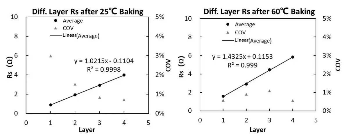
Using the number of layers as the X-axis and Rs as the Y-axis, the relationship between the number of layers and resistance Rs can be obtained, as shown in Figure 9.

Figure 9. Separator Rs after different aging temperature treatments
According to the national standard formula, it can be calculated that the ionic conductivity of the separator after aging temperature treatment at 25°C is 0.803mS/cm, and the ionic conductivity of the separator after aging temperature treatment at 60°C is 0.509mS/cm. It shows that the ion conductivity of the separator after aging treatment at 25°C is higher than that of the separator aged at 60°C.
The main reason is that aging caused by high-temperature storage will cause deposits to appear on the surface of the positive electrode material particles of the battery, which is mainly due to the oxidation of the electrolyte on the surface of the positive electrode particles during the high-temperature storage process. At the same time, sediments may also appear on the surface of the negative electrode, mainly due to the thickening reaction of the SEI film on the negative electrode surface and the decomposition reaction with the electrolyte. These deposits may cover the surface of the membrane and cause pore clogging. At room temperature, the degree of these side reactions is lower and the rate is slower. Therefore, high-temperature aging is more likely to cause the ionic conductivity of the separator to decrease. Therefore, we can determine that the aging process for 48 hours at 60°C may not be suitable for this type of battery.
3. Summary
For diaphragms with different treatment processes and different aging temperatures, IEST has used its own equipment: the multi-channel separator ion conductivity measurement system to quickly complete the assembly of multi-layer diaphragms and conduct ionic conductivity tests, which greatly improves the testing efficiency. Meanwhile, the test results also show that different diaphragm treatment processes and different aging temperatures have a greater impact on the ionic conductivity of the diaphragm.
4. References
[1] Yang Baoquan, Ceramic Coated Diaphragm Modified Lithium Ion Battery Diaphragm, Aging and Application of Synthetic Materials, 2018, 47(1), 67-72.
[2] National standard: GB/T 36363-2018《Polyolefin separator for lithium-ion batterie》.
[3] Wall,Wolfgang,A,et al. Tortuosity Determination of Battery Electrodes and Separators by Impedance Spectroscopy (vol 163, pg A1373, 2016)[J].Journal of the Electrochemical Society, 2017, 164(4).
Subscribe Us
Contact Us
If you are interested in our products and want to know more details, please leave a message here, we will reply you as soon as we can.


