-
iestinstrument
Analysis of Gas Production Behavior Of LFP Cells During Overcharge And Overdischarge Stages
1. Preface
Lithium iron phosphate (LFP Cell) cells are usually based on the LiFePO4 of the olivine structure4 Material coated on aluminum foil as positive electrode, graphite material coated on copper foil as negative electrode, due to its good safety, it has become the most commonly selected cell system for new energy powered vehicles and energy storage power stations. When the LFP cells are charged, the Li+ Migrate to the LiFePO4 On the particle surface, the electrode reaction enters the electrolyte, crosses the diaphragm to the surface of the graphite negative electrode particles, and is embedded in the graphite lattice to form the LiCx Intercalated compound, at the same time, the electron coating flow to the positive electrode aluminum foil fluid, after the external circuit flow to the graphite negative electrode, so that the negative electrode to the charge balance state.
Li+ After unembedding, the cathode material was prepared by LiFePO4 translate Li1-xFePO4. The discharge is just the opposite, the Li inside the cell+ it is removed from the negative electrode graphite lattice, flows through the electrolyte and diaphragm to the positive electrode, and is reembedded in the LiFePO4 at the corresponding position of the lattice, the external circuit electrons flow from the negative copper foil to the positive aluminum foil into the LiFePO4 positive electrode, to reach the charge balance. Figure 1 shows a schematic diagram of the working principle of the LFP cell.
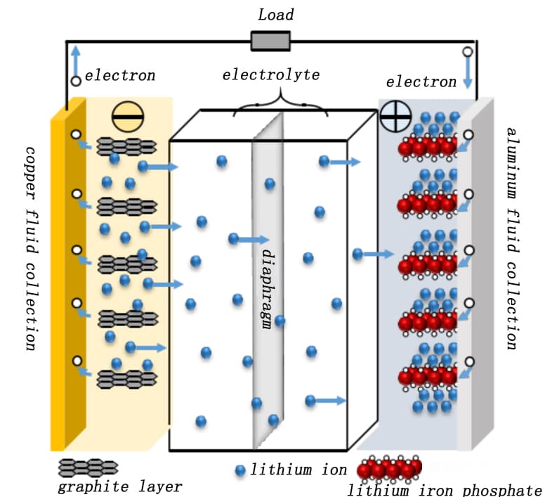
Figure 1. Schematic diagram of the working principle of the LFP full electric cell [1]
In practical application, both overcharge and overdischarge will cause different layer damage to the cell and affect the life of the cell.It is easy to produce lithium precipitation and gas production when overcharge, and easy to lead to copper dendrite and gas production, which will cause lithium cell performance attenuation and even fire and explosion. In this paper, GVM series in situ volume monitoring equipment is selected to monitor the gas production change of lithium iron phosphate(LFP cell) in the process of overcharge and overdischarge in real time, and analyze the gas production types under overcharge and overdischarge conditions combined with gas chromatograph, so as to help further understand the overcharge and overdischarge mechanism of the cells.
2. Experimental Equipment and Test Methods
2.1 Experimental Equipment
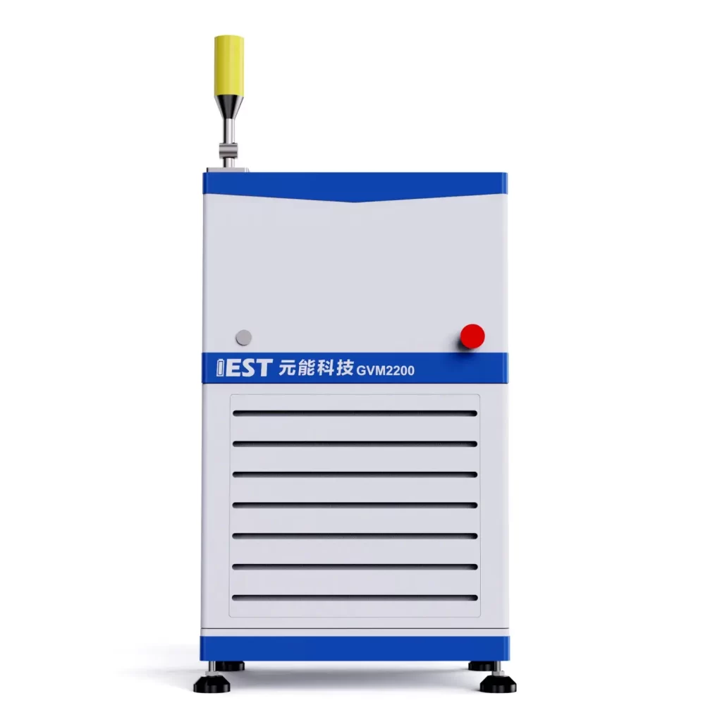
In-situ Battery Gassing Volume Analyzer Model GVM2200(IEST), test temperature range of 20℃~85℃, support dual channel (2 cells) synchronous test, the appearance of the equipment as shown in Figure 2.
Figure 2. Appearance diagram of the GVM2200 equipment
2.2 Cell Overcharge and Discharge Parameters
After the cell is full to 2.5V, hold for 2h, cell a: 0.5C(1.5A) CCCV overcharge to 5V, stop current 0.2mA, maintain; cell b: 0.5C(1.5A) DC overput to 0V and hold;
2.3 Test Method
Initially weigh the cell, m0Put the cell to be tested into the corresponding channel of the device, open the MISG software, set the corresponding cell number and sampling frequency parameters of each channel, and the software automatically reads the volume change, test temperature, current, voltage, capacity and other data. The gas composition test uses GC-2014C gas chromatography, with 1mL of gas removed in the glove box, and different gas concentrations are tested with TCD and FID detectors, respectively. The measurable gas types are shown in Figure 3.

Figure 3. Gas composition that can be tested by FID and TCD detectors
 3. Analysis of the Results of Overcharge and Overdischarge Gas Production
3.1 Overcharge, Overcharge and Discharge, and Volume Change Curve Analysis
As shown in Figure 4, the volume and voltage change curve of the lithium ion from the positive electrode during the normal charging stage of the charging cell, the voltage increases, as the voltage increases, and the cell volume increases, and the process of graphite can reach 10%[2]。Graphite negative electrode is a typical phased interlayer lithium embedding process. After lithium ion is embedded, the layer keeps the plane. The graphite layer and the embedded layer are arranged in parallel, and every third layer, 2 and one layer are regularly embedded to form Li-C interlayer compounds (LiCx) with different phases such as 3,2 and 1.The initial stage is stage 4, and the state of each three layer of lithium ion is called stage 3, which corresponds to Li0.3C6Compounds, with a relative lithium concentration of 33.33%.Each two layers of lithium embedding is stage 2, corresponding to Li0.5C6, The relative concentration was 50%.After the graphite is completely embedded with lithium, the LiC is formed6Compound, one lithium ion embedded in the middle of every six hexagonal carbon atoms, is a 100% relative lithium-embedded concentration[2].
As shown in Figure 5 shows the change of the negative state in the normal charging stage of lithium ion cell. The above lithium embedded stage is in a completely ideal state. The actual lithium embedded state inside graphite is more complex, which is often a mixture of multiple stages.The volume change of the corresponding cell charging stage is mainly related to the structural phase change caused by the negative electrode lithium embedding[5], In the initial stage of charging, with the increase of lithium embedded, the volume of graphite lattice expands, forming the expansion curve with the larger slope of the first stage, the lattice size of graphite changes least between x=0.2 and 0.6, and the expansion appears a platform curve; LiC6The layer spacing of the phase is significantly greater than that of Li0.5C6each other.equal LiC6The maximum slope for the increase of the corresponding thickness change occurs in the presence of the phase.
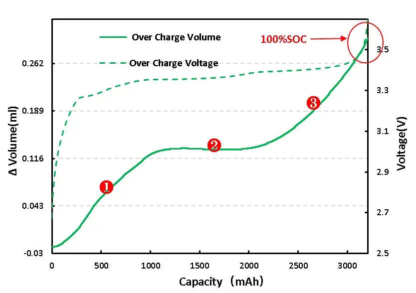
Figure 4. Volume change in the normal charging stage of the overcharging cell

Figure 5. (1)Changes in graphite negative electrode state during normal charging of lithium-ion batteries[2]
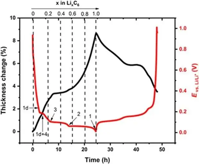
Figure 5. (2)Graphite volume expansion curve[5]
For full LFP cell continue to charge, get the voltage and volume change curve as shown in figure 6 (A), from the volume changes, and overcharge to 110%SOC volume has obvious inflection point, can preliminarily judge the cell has begun to produce gas, the corresponding voltage is 5V, continuous voltage in 5V, volume change is still in the increasing trend, and the cell can see obvious bulge phenomenon.
Cell process of voltage and volume change curve as shown in 6(B), the early volume change no obvious change, and to 0.4V volume change has obvious inflection point, preliminary judgment of the cell gas, continue to keep the cell in the low voltage condition, the volume change has the trend of continuous growth, at the same time also has a slight bulge phenomenon.
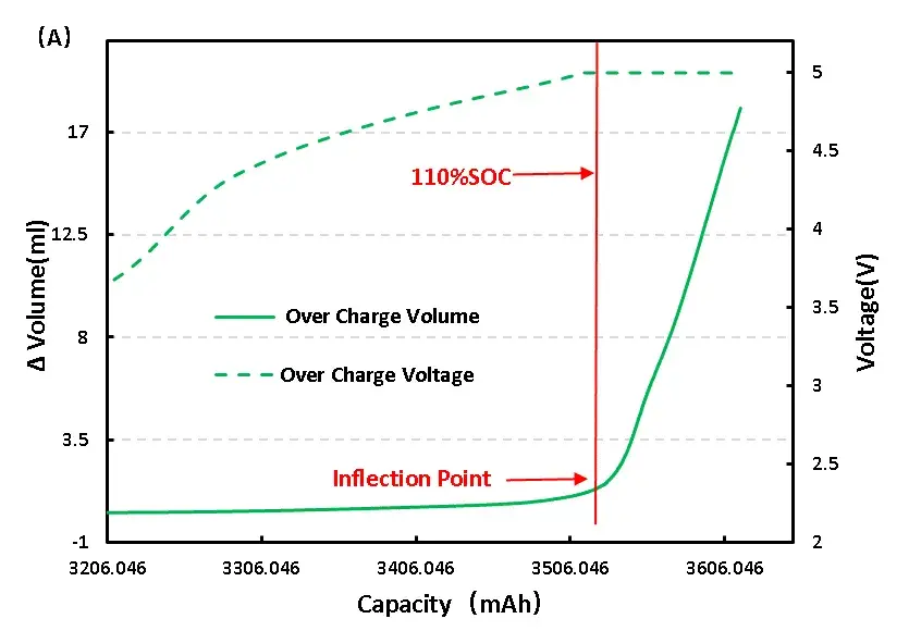
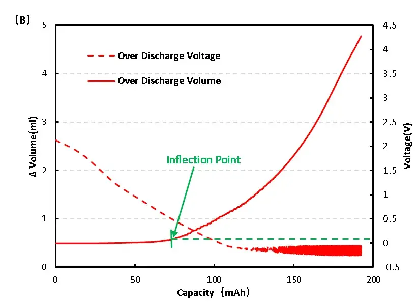
Figure 6. Change of overcharge and overdischarge volume of LFP cell
3.2 Analysis of the Composition of Overcharge and Overdischarge Gas Production
1mL of gas was removed from the gas producing cells after overcharge and overdischarge and qualitatively analyzed by gas chromatography. As shown in Figure 7,8 and Table 1, the gas producing components of overcharge and LFP cells, H2All have a high proportion, which may be due to the gas produced by water absorption on the negative electrode, according to the results[4], Under vacuum, when the water begins to deattach at about 350K, the activation energy of its deattach is 1.3ev, and the main gas produced is H2. This is also the actual production process of lithium ion cell, the need to strictly control H2O One of the causes of impurities; besides, high voltage may produce H2. From the gas phase composition detection results, for overcharge and overdischarge gas cells except H2. In addition, the overcharging core and CO, CO2、C2H6、CH4、reach C2H2、Gas, this is mainly caused by the side reaction of the cell material and the electrolyte, in which the overcharged gas cell in addition to the same gas type, but also detected a high content of CO and CO2 ,Gas, which is also consistent with the previously reported overcharged gas production composition of the LFP cells.
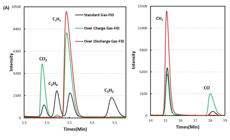
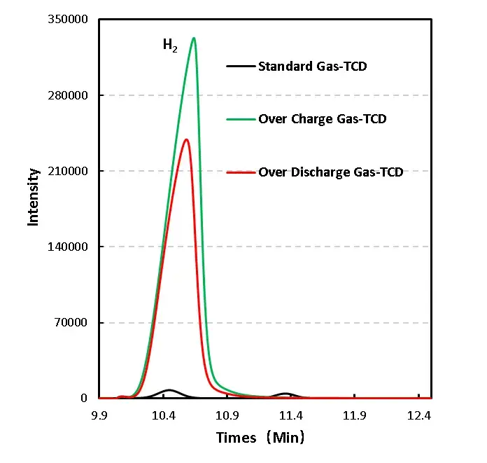
Figure 7. GC test results of overcharged and overdischarged gas production components of LFP cells
Table 1. Comparison Table of Overcharge and Overproduction Components of LFP Cells
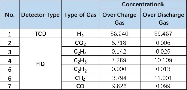
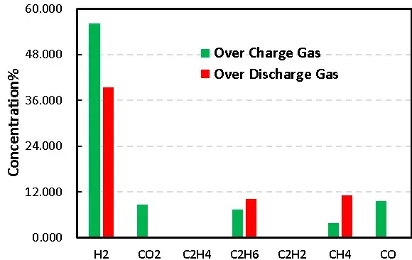
Figure 8. Comparison of overcharge and overdischarge gas production of LFP cells
4. Summary
This paper adopts a controlled temperature dual channel in situ gas volume monitoring instrument, combined with gas chromatography, the LFP cell gas behavior and gas composition qualitative quantitative analysis, defined the process of gas changes and gas composition, can be used as an effective means of lithium ion cell gas behavior analysis.
5. References
[1] Zheng Zhikun Cheng.Research on lithium iron phosphate energy storage overcharged thermal runaway and gas detection safety early warning [D].Zhengzhou University.
[2] Reynier Y, Yazami R, Fultz B, et al. Evolution of lithiation thermodynamics with the graphitization of carbons[J].Journal of Power Sources, 2007, 165(2):552-558.
[3] Yang L, Chen H S, Song W L, et al. Effect of Defects on Diffusion Behaviors of Lithium-Ion Battery Electrodes: In Situ Optical Observation and Simulation[J].ACS Applied Materials & Interfaces, 2018, 10(50).
[4] Kajiura H, Nandyala A, Bezryadin A. Quasi-ballistic electron transport in as-produced and annealed multiwall carbon nanotubes[J].Carbon, 2005, 43(6):1317-1319.
[5] H.Michael, F.Iacoviello, T.M.M.Heenan, A.Llewellyn,J.S.Weaving, R.Jervis, D.J.L.Brett, and P.R.Shearing. A Dilatometric Study of Graphite Electrodes during Cycling with X-ray Computed Tomography[J]Journal of the Electrochemical Society, 2021,168: 010507.
Subscribe Us
Contact Us
If you are interested in our products and want to know more details, please leave a message here, we will reply you as soon as we can.


