

LMFP material (lithium manganese iron phosphate, LiMnxFe1−xPO₄) is an olivine-structured cathode material that bridges the gap between LFP and NCM: it shares LFP’s structural stability and safety while raising the charging voltage from LFP’s 3.4 V to approximately 4.1 V, increasing theoretical energy density by 15–20% through manganese doping. LMFP’s main limitation is intrinsically poor electronic conductivity—approximately 10−13 S/cm, far below LFP’s already-low 10−9 S/cm and NCM’s 10−3 S/cm—because its olivine crystal structure lacks the continuous edge-sharing octahedral network that enables electron transport in layered oxides. Carbon coating and ion doping are the two primary strategies for improving LMFP electronic conductivity and ionic conductivity. This article reviews current industrial synthesis routes, modification strategies, and the two-probe versus four-probe DC conductivity test methods used to evaluate cathode powder conductivity, including the IEST PRCD3100 powder resistivity and compaction density tester.
Current lithium-ion battery cathode materials are dominated by lithium cobalt oxide (LCO), ternary materials (NCM), and lithium iron phosphate (LFP). Over the past one to two years, growth in electric vehicles and energy storage deployment has intensified industry focus on battery safety. Beyond battery design innovations (such as blade-cell and CTP pack architectures), new cathode material development remains critical to advancing both safety and energy density.
LFP has become the dominant cathode material for electric vehicles and energy storage due to its high safety, but LFP energy density has nearly reached its practical ceiling, leaving little room for further improvement. Lithium manganese iron phosphate (LMFP material) shares LFP’s olivine crystal structure and inherits its chemical stability and excellent safety performance. Critically, the manganese doped into LMFP material raises the charging voltage plateau from LFP’s 3.4 V to approximately 4.1 V, increasing the theoretical energy density of LMFP batteries by 15–20% and meaningfully extending vehicle driving range.
LMFP material offers better safety performance than NCM material and higher energy density than LFP material. It also has low dependence on rare or critical metals and can be manufactured on the same production line as LFP, giving it a clear cost advantage for manufacturers transitioning existing capacity. Table 1 details the performance comparison between LMFP and other cathode materials.
| Property | LMFP | LFP | NCM |
|---|---|---|---|
| Material Structure | Olivine Structure | Olivine Structure | Nickel-cobalt-manganese ternary materials |
| Material Source | Phosphorus and Iron Resources Abundant | Phosphorus and Iron Resources Abundant | Cobalt Resource Scarce |
| Theoretical Specific Capacity (mAh/g) | 170 | 170 | 278 |
| Actual Specific Capacity (mAh/g) | 130–150 | 130–150 | 150–200 |
| Voltage Platform (V) | 4.1 | 3.4 | 4.3 |
| Theoretical Energy Density (Wh/kg) | 697 | 578 | 1204 |
| Actual Density (g/cm³) | 2.4 | 2.3 | 3.7–3.9 |
| Electrical Conductivity | 1013 | 109 | 103–106 |
| Thermal Stability | Stable | Stable | Decomposes at 300°C |
| Cost | Low | Low | High |
| Safety | Good | Good | Moderate |
| Theoretical Life | Good | Good | Moderate |
| Cycle Life (times) | 2000 | 2000 | 800–2000 |
The synthesis methods for LMFP material and LFP material are largely the same—primarily high-temperature solid-state synthesis, hydrothermal synthesis, and co-precipitation. There is no single unified industry standard for the LMFP preparation process route; leading manufacturers use distinct technical approaches:
The one-dimensional lithium-ion conduction channel characteristic of olivine-type cathode materials fundamentally limits their ionic conductivity. In terms of electron transport, LMFP electronic conductivity is lower than LFP despite both being semiconducting: LFP electronic conductivity is approximately 10−9 S/cm, NCM electronic conductivity is approximately 10−3 S/cm, while LMFP electronic conductivity is only approximately 10−13 S/cm.
Structurally, LMFP material lacks the continuous edge-sharing FeO₆ (MnO₆) octahedral network found in layered oxide cathodes; instead, octahedra are connected only through PO₄ tetrahedra (Figure 1). This means LMFP cannot form the continuous Co–O–Co conduction pathway present in lithium cobalt oxide, restricting lithium-ion movement to a strictly one-dimensional channel. This structural constraint is the root cause of LMFP’s low electronic conductivity and its correspondingly poor high-rate charge/discharge performance. Conductivity improvement strategies for LMFP material focus primarily on two approaches: carbon coating (which mainly improves electronic conductivity) and ion doping (which mainly improves lithium-ion diffusion coefficient and ionic conductivity).
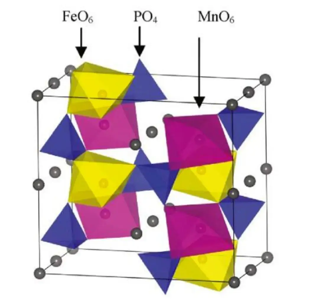
Figure 1. Schematic structure of olivine-type LMFP material[1]— PO₄ tetrahedra connect FeO₆/MnO₆ octahedra, preventing the continuous edge-sharing network that enables higher conductivity in layered cathodes
Adding an appropriate amount of carbon during LMFP material synthesis improves conductivity while also preventing particle-to-particle contact and inhibiting particle agglomeration and growth, making it easier to obtain nano-scale cathode particles.[2,3] Smaller particle size effectively reduces the lithium-ion diffusion distance within active particles, enabling improved rate performance. Carbon coating also reduces the contact area between active material and electrolyte, suppressing side reactions and improving high-temperature performance and cycling stability.
Carbon coating for LMFP material is generally implemented through two routes: mixing the finished LMFP product with a carbon source and calcining under a reducing atmosphere, or adding the carbon source directly into the raw material mixture before drying and high-temperature sintering to form an integrated LMFP/C composite. As one example, Oh and co-workers used ultrasonic spray pyrolysis to synthesize LiMnxFe1−xPO₄ powder,[4] then ball-milled it with a carbon source to obtain carbon-coated olivine-type cathode material. The resulting material delivered first-discharge specific capacities of 150 mAh/g at 0.5C and 121 mAh/g at 2C, with the electrochemical performance improvement attributed to close bonding between primary particles and carbon and uniform carbon coating coverage.
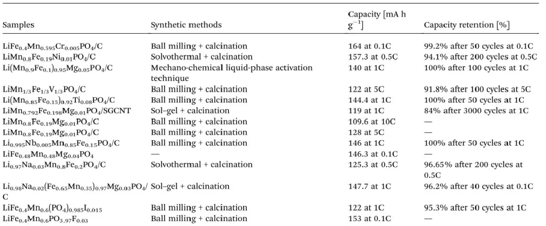
Beyond surface carbon coating, ion doping is a common approach for improving LMFP material’s lithium-ion diffusion coefficient and ionic conductivity. Ion doping creates Li-site or Fe/Mn-site defects within the LMFP crystal lattice, introducing vacancies or modifying inter-atomic bond lengths in ways that facilitate Li⁺ movement through the lattice and improve overall electrochemical performance.[5] Compared with morphology control and surface coating, ion doping’s key advantage is that it can increase bulk energy density while having minimal effect on the material’s vibrational/packing density—favorable for improving rate performance without sacrificing volumetric capacity. Table 2 summarizes recent literature data on elemental doping strategies for LMFP material performance.
Table 2. Summary of elemental doping effects on LMFP material electrochemical performance[6]
The modification strategies above can effectively improve LMFP material conductivity and electrochemical performance. For performance characterization, researchers typically assemble coin cells or pouch cells for electrochemical testing, or measure EIS to assess impedance changes resulting from modification. However, both approaches are relatively slow and indirect for screening material modifications. A faster, more direct question is: how can LMFP electronic conductivity be measured accurately before and after material modification, without full cell assembly?
By Ohm’s law (R = U/I), the resistance of a conductor can be calculated from the current passing through it and the voltage drop across it. Combined with the geometric dimensions of the test sample, this resistance value can be converted to conductivity using the following formula:
\[\sigma_e = \frac{1}{\rho} = \frac{l}{RS}\]
\(\sigma_e\): Conductivity, \(\rho\): Resistivity, \(R\): Resistance, \(l\): Material thickness, \(S\): Area of material
This general approach is referred to as the DC method: the electrode material conducts via a mixture of ionic and electronic transport, and during DC polarization testing, the initially high transient mixed current quickly decays to a stable electronic current—allowing the electronic conductivity component to be isolated and measured. The DC method includes two implementations: two-probe method and four-probe method.
Through extensive comparative testing, IEST has found that the two-probe method is better suited to samples with moderately higher resistance, such as LCO and low-nickel NCM cathode materials, while the four-probe method is better suited to samples with lower resistance, such as graphite anode material and various conductive agents. For samples in the ohmic resistance range—including carbon-coated LMFP and LFP—both methods are equally applicable, and comparative testing shows no significant difference between the two methods’ results for these materials.
Based on these findings, IEST has developed a dual-principle, dual-function instrument capable of accurately measuring both higher- and lower-resistance samples: the Powder Resistivity & Compaction Density Tester (PRCD3100, IEST). During testing, the instrument applies controlled pressure to the powder sample—up to 5 tonnes—while synchronously collecting resistance, resistivity, conductivity, and compaction density data, displaying all parameters in real time on the software interface.
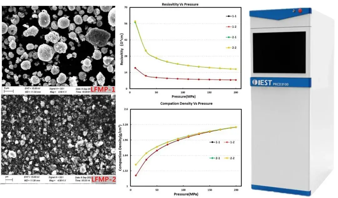
Figure 3. IEST PRCD3100 Powder Resistivity & Compaction Density Tester — schematic and LMFP material conductivity test data; supports dual two-probe and four-probe measurement up to 5 tonnes applied pressure
[1] Osorio-Guillén J M,Holm B,Ahuja R,et al. A theoretical study of olivine LiMPO4 cathodes[J]. Solid State Ionics, 2004, 167(3-4): 221-227.
[2] Wang Y, Hu G, Cao Y, et al. Highly atom-economical and environmentally friendly synthesis of LiMn0.8Fe0.2PO4/rGO/C cathode material for lithium-ion batteries[J]. Electrochimica Acta, 2020,354:136743.
[3] Kosova N V, Podgornova O A, Gutakovskii A K. Different electrochemical responses of LiFe0.5Mn0.5PO4 prepared by mechanochemical and solvothermal methods[J]. Journal of Alloys and Compounds, 2018, 742: 454-465.
[4] Oh S M, Jung H G, Yoon C S, et al. Enhanced electrochemical performance of carbon-LiMn1−x FexPO4 nanocomposite cathode for lithium-ion batteries[J]. Journal of Power Sources, 2011, 196(16): 6924-6928.
[5] Budumuru A K, Viji M, Jena A, et al. Mn substitution controlled Li-diffusion in single crystalline nanotubular LiFePO4 high rate-capability cathodes: Experimental and theoretical studies[J]. Journal of Power Sources, 2018, 406: 50-62.
[6] Yang L , Deng W , Xu W ,et al. Olivine LiMnxFe1-xPO4 cathode materials for lithium ion batteries: restricted factors of rate performances[J].Journal of Materials Chemistry A, 2021, 9: 14214–14232.
LMFP (lithium manganese iron phosphate, LiMnxFe1−xPO₄) is an olivine-structured cathode material that combines manganese and iron in the same lattice as LFP. Compared to LFP, LMFP raises the operating charge voltage from approximately 3.4 V to 4.1 V through manganese substitution, delivering a 15–20% increase in theoretical energy density while retaining LFP’s olivine-structure safety and stability advantages. Compared to NCM ternary cathode material, LMFP offers better safety performance (no risk of oxygen release from a layered oxide structure) and lower dependence on nickel and cobalt, though NCM still leads in absolute energy density and electronic conductivity (10⁻³ S/cm for NCM vs ~10⁻¹³ S/cm for uncoated LMFP).
LMFP material increases the cathode charging voltage plateau from LFP’s 3.4 V to approximately 4.1 V, a direct result of manganese substitution in the olivine lattice. This higher operating voltage translates into a theoretical energy density increase of approximately 15–20% over LFP at the cathode material level. The exact energy density gain at the cell level depends on the specific Mn:Fe ratio used, the degree of carbon coating and ion doping applied, and the overall cell design—but the 15–20% range represents the typical material-level improvement reported for optimized LMFP formulations relative to LFP.
LMFP electronic conductivity is approximately 10⁻¹³ S/cm—substantially lower than LFP’s already-low 10⁻⁹ S/cm and far below NCM’s 10⁻³ S/cm. This gap arises from crystal structure: both LMFP and LFP have an olivine structure where octahedral MO₆ units (M = Fe, Mn) are connected only through PO₄ tetrahedra, rather than sharing edges directly as in layered oxides like NCM. This prevents formation of a continuous electron-conduction pathway and restricts lithium-ion transport to a strictly one-dimensional channel within the lattice. The manganese component in LMFP further reduces conductivity relative to pure LFP, making carbon coating and ion doping essential modification strategies for any practical LMFP material application.
Because both LFP and LMFP cathode materials have intrinsically low electronic conductivity, conductive agents are essential formulation components. Conductive carbon black (Super-P, KS-6 type) is the most widely used additive, providing a continuous electron-conduction network between active particles and the current collector. Carbon nanotubes (CNT) and graphene-based conductive agents are increasingly used at lower loadings to achieve equivalent or superior conductivity with less volume penalty to active material loading. For LMFP material specifically, in-situ carbon coating during synthesis (forming an LMFP/C composite) is typically combined with conductive carbon black in the electrode formulation, since surface carbon coating alone improves particle-level conductivity but a separate conductive network is still needed at the electrode level for efficient charge collection.
The two-probe and four-probe methods are both DC resistance measurement techniques used to determine the electronic conductivity of battery powder materials. In the two-probe method, the same pair of electrodes both supplies current and measures voltage, so contact resistance between the electrode and sample is included in the measurement—making it more suitable for higher- resistance materials (such as LCO and low-nickel NCM) where contact resistance is a small fraction of total resistance. In the four-probe method, separate electrode pairs supply current and measure voltage, eliminating contact resistance from the measurement—making it more accurate for lower-resistance materials such as graphite anode powder and conductive agents, where contact resistance would otherwise dominate the signal. For materials in the ohmic resistance range, including carbon-coated LMFP and LFP, comparative testing shows both methods produce equivalent results, which is why instruments such as the IEST PRCD3100 support both measurement principles in a single platform.
