-
iestinstrument
How To Improve Electrolyte Wetting Level
1. Preface
The degree of electrolyte wetting is one of the key factors affecting the performance of lithium-ion batteries such as kinetics, cycle life, and safety and reliability, etc. A good wetting effect can form a uniform interface between the solid-liquid, which is favorable for the electrochemical reaction, and reduce the interfacial resistance between the positive and negative electrode materials and the electrolyte. This interface contributes to the generation of (Solid Electrolyte Interface) SEI film, which enhances the cycling stability and safety of the battery cell[1-3].
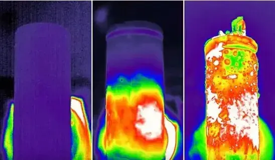
If the wetting effect of the electrolyte is not satisfactory, it will make the transport path of lithium ions farther during the charging and discharging process, reduce the shuttling efficiency of lithium ions between the positive and negative electrodes, and affect the kinetic performance of the battery cell. Incomplete infiltration may lead to problems such as active substance stripping and lithium dendrite growth, which will lead to an increase in internal resistance and a decrease in capacity of the core, accelerating the aging process of the core, and more seriously, may cause the core to become locally overheated during the charging and discharging process, resulting in thermal runaway that leads to safety problems such as fires and explosions (Figure 1).

Figure 1. Thermal runaway of battery cell
2. Strategies to Improve Electrolyte Wetting
For the problem of poor electrolyte wetting, it can be improved by adjusting the electrolyte formulation, modifying the parameters of the production process of the electrode core and other programs:
2.1 Electrolyte Formulation Optimization
Optimize solvents, salt concentration and additives to improve wettability (lower contact angle), viscosity and surface tension. For example:
-
Use low-viscosity solvents or solvent blends.
-
Add small amounts of wetting agents or co-solvents that enhance electrode surface affinity.
-
Balance additives that improve SEI or stability against the viscosity penalty they may introduce.

Figure 2. Schematic diagram of the contact angle between the electrolyte and the electrode
2.2 Improvement of pre-process technology
Adjust active material morphology, conductive carbon distribution and binder formulation:
-
Increase specific surface area where appropriate to speed infiltration.
-
Optimize slurry rheology, coating thickness and drying to improve pore connectivity.
2.3 Electrode compaction density
Porosity and compaction density strongly influence wetting:
-
Avoid over-compaction: high compaction can reduce porosity and hinder penetration.
-
Tune calendering (roll pressure) to a compromise between low impedance and adequate infiltration.
2.4 Cell-level design & assembly
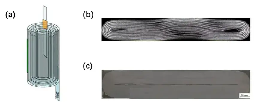
Winding tension, separator selection and hot-press parameters affect internal gaps and flow paths:
-
Control winding/stack tightness to allow electrolyte access without causing core deformation.
-
Choose separator thickness and wettability compatible with the electrolyte.

Figure 3. (a) Schematic diagram of the battery cell, (b) Schematic diagram of the cross-section of the battery cell before hot pressing (c) after hot pressing
2.5 Improvement of liquid injection process
One of the most conventional ways to improve the wetting effect of electrolyte is to adjust the liquid injection process. From the liquid injection method, liquid injection static temperature and time, liquid injection conditions and other aspects can effectively improve the electrolyte wetting effect. For example, the electrolyte wettability of lithium-ion batteries can be improved by vacuum liquid injection. Liquid injection under vacuum conditions is not only conducive to discharging the gas in the core, but also reduces the resistance of the gas to electrolyte injection, so that the electrolyte is in direct contact with the pole piece, thereby reducing the wetting time and improving the degree of wetting. After liquid injection, the electrolyte is usually left to stand at high temperature, under which the electrolyte can better penetrate into the interior of the core and the pores of the electrode material, thus improving the contact area between the electrolyte and the electrode and the reaction activity.
3. Quantitative testing: Electrolyte Wetting Test System(EWS)
Based on the importance of electrolyte wetting for battery cells, IEST has developed an electrolyte wetting test system, which can quantify the difference of electrolyte wetting between different electrode and battery cells, and provide an effective means of evaluating electrolyte wetting.
3.1 Electrode Electrolyte Capillary Wetting System
Figure 4a shows the schematic principle of the capillary infiltration method. The electrolyte is injected into the capillary tube, and after the capillary glass tube is vertically contacted with the surface of the pole piece, the capillary liquid level decreases as the electrolyte continues to infiltrate the coating. The visual recognition system records the capillary liquid level height in real time, and the dynamic evolution of the liquid level height is the electrolyte infiltration process in real time, and the amount of height change is the amount of electrolyte infiltration. As shown in Fig. 4b, the values of electrolyte liquid level decrease in 50s and 100s for sample 1 are significantly larger than those for sample 2, which indicates that the electrolyte has a better infiltration ability in sample 1.
Figure 4.(a) Schematic diagram of the principle of capillary infiltration method, (b) Capillary infiltration curves for different cathode electrodes
3.2 Electrolyte weight infiltration system
Figure 5a shows the schematic diagram of the weight infiltration method. The electrode/battery cell is suspended under the corresponding balance and infiltrated in the electrolyte, which will climb upward with the increase of time, at which time the weight change of the balance can be used to characterize the electrolyte infiltration amount and infiltration rate of the pole piece and bare core in real time. Measurements were made on pole pieces with different compaction densities, in which the compaction density of sample A was smaller than that of sample B. From the measurement results (Figure 5b), the immersion K value of sample A was larger than that of sample B, i.e., the larger the compaction density the worse the electrolyte immersion.
Figure 5. (a) Schematic diagram of the principle of the weight infiltration method, (b) Infiltration curves of the weight method for electrodes with different compaction densities
3.3 Electrolyte height infiltration system
Figure 6a shows the schematic principle of the height infiltration method. The pole piece is placed vertically and infiltrated in the electrolyte, and the infiltration height of the electrolyte in the pole piece is recorded in real time by the equipped high-precision visual acquisition system to characterize the infiltration rate of the electrolyte in real time. Figure 6b shows the measurement results of the height method for different negative electrodes, from which the height method can also distinguish the difference in electrolyte infiltration of different electrodes.
Fig. 6.(a) Schematic diagram of the principle of the height infiltration method, (b) Infiltration curves of the height method with different cathode electrodes
4. Practical recommendations
-
Screen electrolyte candidates with capillary and weight infiltration tests before cell prototyping.
-
Track both viscosity and contact angle — viscosity often dominates capillary wetting.
-
Implement vacuum filling and controlled filling temperature in production for consistent wetting.
-
Balance compaction density vs. wettability during electrode calendering.
-
Use EIS (electrochemical impedance spectroscopy) after filling to verify interfacial resistance and confirm effective wetting.
5. Summary
Reliable electrolyte wetting is essential for high-performance, durable and safe lithium-ion cells. IEST has developed an electrolyte wetting test system(EWS Series), which can evaluate the wetting ability of electrolyte from the level of electrode and battery, and combining smart electrolyte formulation, optimized electrode processing, controlled filling, and quantitative testing (capillary, weight, height methods) allows R&D and production teams to ensure consistent battery electrolyte level and superior cell performance.
6. FAQ (focused on electrolyte wetting & battery electrolyte level)
Q: What is the fastest way to screen electrolyte wettability?
A: Use a capillary infiltration test (visual) for rapid ranking; follow up with weight infiltration for quantitative uptake.
Q: How does compaction density affect electrolyte wetting?
A: Higher compaction reduces porosity and can hinder wetting. Optimize calendering to balance conductivity and infiltration.
Q: Can filling temperature improve battery electrolyte level uniformity?
A: Yes — modestly increasing filling temperature lowers viscosity and improves infiltration speed and uniformity across the cell.
Q: How do I detect incomplete wetting in production cells?
A: Monitor battery electrolyte level during soak (weight method), run post-fill EIS to detect high interfacial resistance, and visually inspect for bulging or black spots after cycling.
Q: Are wetting additives always beneficial?
A: Additives can improve wetting but often increase viscosity or alter SEI chemistry. Always evaluate trade-offs by combined wetting and electrochemical testing.
7. References
[1] Zheng Honghe et al. eds. Electrolytes for lithium ion batteries. Beijing: Chemical Industry Press, 2007.01.
[2] Wang B L, Wang J P, Zhang L, et al. Adsorptive Shield Derived Cathode Electrolyte Interphase Formation with Impregnation on LiNi0.8Mn0.1Co0.1O2 Cathode: A Mechanism-Guiding-Experiment Study[J]. ACS Applied Materials & Interfaces, 2024:16, 38, 50747-50756.
[3] Zhang Shuanghu. Progress in Electrolyte Wetting for Lithium Ion Battery [J]. Chemistry World,2021,62(03):129-136.
[4] Yao N, Yu L, Fu Z H, et al. Probing the origin of viscosity of liquid electrolytes for lithium batteries[J]. Angewandte Chemie International Edition,2023:e202305331.
Contact Us
If you are interested in our products and want to know more details, please leave a message here, we will reply you as soon as we can.


