

Volume expansion in lithium-ion batteries refers to the reversible and irreversible dimensional change of a cell caused by electrode lithiation/delithiation, gas evolution, and internal stress relaxation. Lithium-ion batteries undergo volume expansion during formation, cycling, storage, and overcharge, stemming from both structural changes and gas evolution.
The charge discharge rate, commonly expressed as C-rate (a measure of current relative to a cell’s rated capacity, e.g. 1C fully charges or discharges a cell in one hour), determines the speed of lithium (de)intercalation and is accompanied by varying degrees of heat generation or lithium plating. Researchers often include a rest period after charge or discharge to allow the cell to stabilize, mitigating thermal and polarization effects. But how does cell volume behave during this rest phase?
This study investigates the impact of C-rate by in-situ monitoring the volume expansion of Lithium Cobalt Oxide(LCO)/Graphite pouch cells during rest after different charge discharge rate cycles.
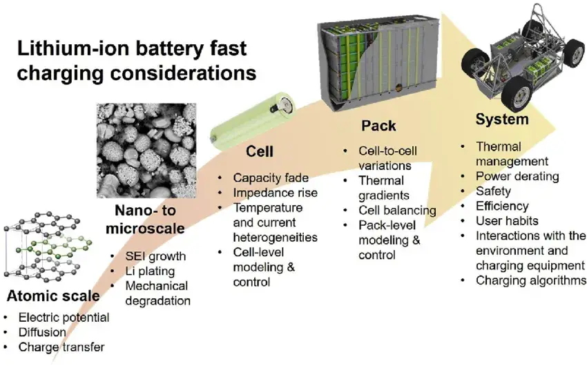
Figure 1. Various factors affecting the fast charging of lithium-ion batteries[1]
The In-situ Gassing Volume Monitor GVM2200 from IEST was used (Figure 1). This instrument allows precise temperature control from 20°C to 80°C and real-time monitoring of cell volume changes.
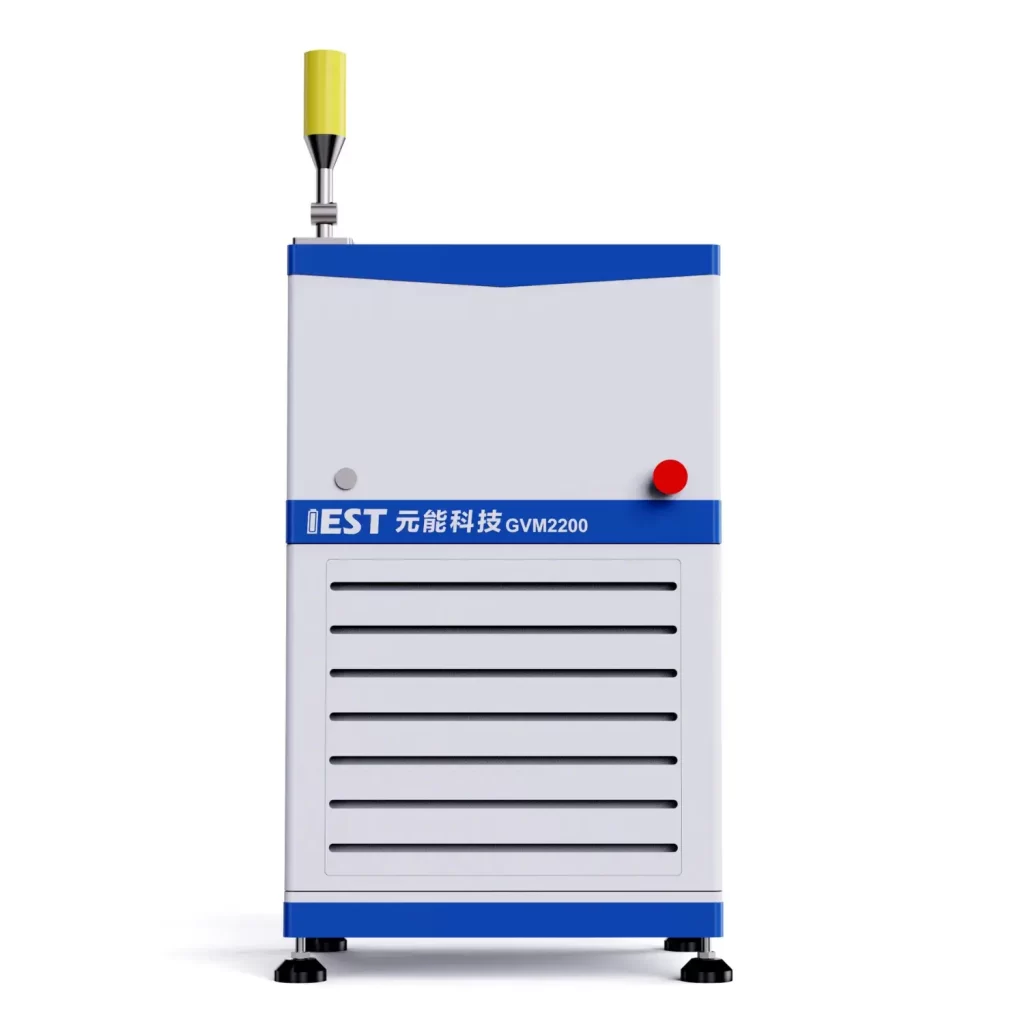
Figure 2. In-Situ Battery Gassing Volume Analyzer (GVM2200)
The test cell specifications are listed in Table 1. Four experimental groups with different charge-discharge protocols were defined (Table 2). Each cycle concluded with a one-hour rest period. The cells were then placed in the GVM2200 with the oil bath set to 25°C for continuous volume monitoring.
| Information of Cell | |
|---|---|
| System | LCO/Graphite |
| Capacity | 2000mAh |
| Voltage | 2.8-4.35V |
| Model | Pouch Cell-345877 |
| Step | 1st cycle | 2nd cycle | 3rd cycle | 4th cycle |
|---|---|---|---|---|
| CC | 1.0C-4.35V | |||
| CV | 无 | 0.1C | 0.05C | 0.025C |
| Rest | 60min | |||
| DC | 1.0C | 1.0C | 0.5C | 0.25C |
| Rest | 60min | |||
Note: *Four distinct protocols were tested, varying the constant current (CC) charge rate, the inclusion of a constant voltage (CV) phase, and the discharge rate. All protocols included a 1-hour rest after both charge and discharge.*
State of Charge (SOC) directly drives volume expansion during CC charging, while Depth of Discharge (DOD, the percentage of capacity removed relative to full capacity) drives volume contraction during CC discharging. During the CC charge phase, volume increased steadily with rising SOC, primarily due to graphite intercalation. Upon entering the CV and subsequent rest phase, the cell volume began to contract, gradually stabilizing.
During the CC discharge phase, volume contracted as DOD increased. A notable initial anomalous expansion was observed at the start of discharge, which diminished as the discharge rate decreased. Volume continued to decrease during the post-discharge rest before stabilizing.
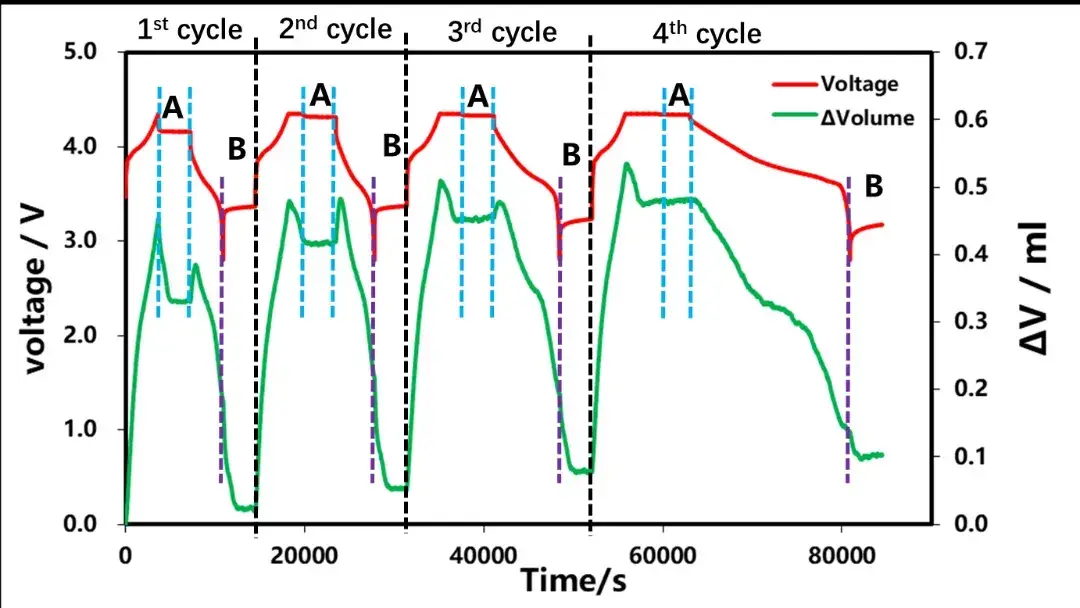
Figure 3. Cell voltage and volume change curves under different charge-discharge currents.
Whether a cycle includes a constant-voltage (CV) charge phase — a charging step in which voltage is held constant while current tapers to a low cutoff — determines how much volume relaxation occurs during the subsequent rest period. Zooming into the post-charge rest periods (Area ‘A’ in Figure 3) reveals a key trend. The first cycle, which lacked a CV phase and ended with a 1C charge rate cutoff, showed significant volume contraction during the 1-hour rest, with contraction lasting approximately 1500 seconds before stabilizing.
In contrast, cycles 2–4 included a CV phase that reduced the cutoff current to below 0.1C. For these cycles, the volume contraction primarily occurred during the CV phase itself, and the subsequent rest period showed minimal further volume change. Without a CV phase, the high internal polarization at the end of a CC charge requires a substantial rest period (≥30 minutes) for stress and strain to release and reach a steady state.
| Cycle | CV phase | Charge cutoff | Volume contraction during rest | Time to stabilize |
|---|---|---|---|---|
| 1 | None | 1C (CC only) | Significant | ~1500 s |
| 2-4 | Yes | <0.1C | Minimal | Rapid |
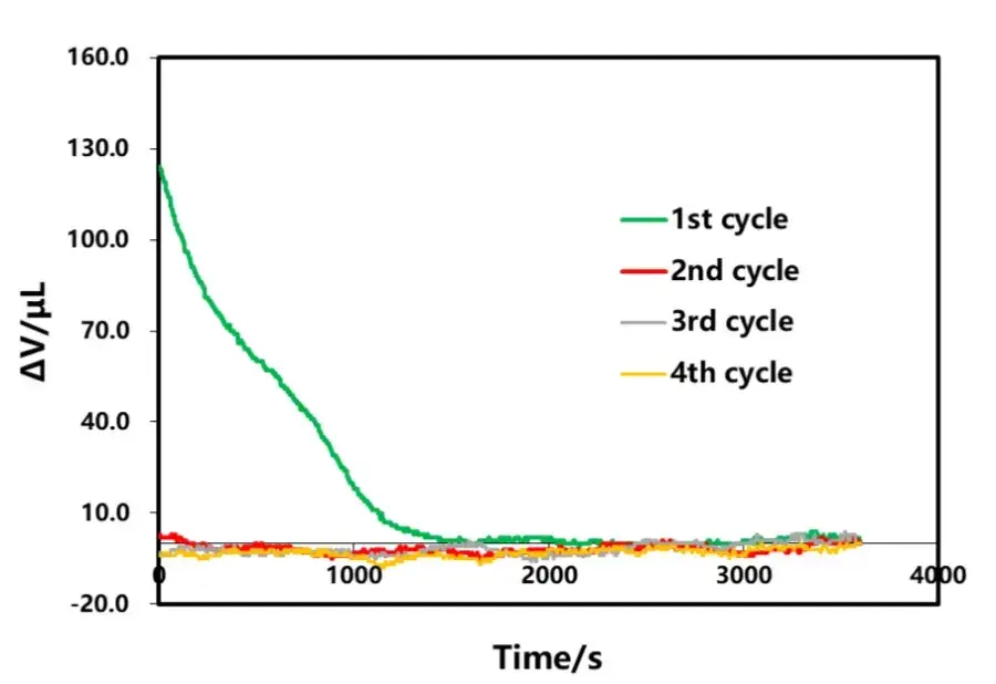
Figure 4. The effect of charge cutoff current on volume change during rest
In order to further explain the process of lithium-ion transmission and charge state evolution in the constant current-constant pressure charge process, the mechanical-electrochemical model is used to study the distribution of lithium concentration, stress and strain in the charging process.
During the constant flow charging phase, lithium-ion are continuously embedded in the graphite layer, which leads to structural swelling. As the SOC continuously grows, the volume constantly expands. When the constant current charging is completed, the lithium ion concentration in the electrolyte, the lithium concentration in the negative electrode particles, the strain, and the stress are as shown in Figure 5. Figure 5 (a) shows that the closer the cathode fluid collection is, the higher the lithium-ion concentration in the electrolyte is. This is because the positive / negative particles near the diaphragm are preferentially lithium / lithium. At the end of constant current charging, the degree of lithium removal / lithium removal of the particles near the diaphragm is greater than that of the particles near the fluid collection. From Figure 5 (b), higher lithium concentration in the negative particles close to the diaphragm. This is because the electrolyte in the negative region away from the diaphragm has a longer lithium diffusion distance than the negative particles near the diaphragm, allowing the lithium-ion reaching the anode to be preferentially inserted into the particles close to the diaphragm.
In the negative electrode particles near the diaphragm, the solid-phase lithium concentration is higher, so their strain is also higher, as shown in Figure 5 (c). Meanwhile, the strain is greater on the free surface of the particles, but less so on the contact surface between the particles and between the particles and the boundary. This is because the insertion of lithium ions causes the volume swelling of the particles. The free surface of the particles expands outward, leading in greater deformation. However, the deformation on the contact surface is smaller under the constraints of adjacent particles and boundaries. Figure 5 (d) shows that the stress distribution is opposite to the strain distribution. This is because the free surface of the particles is unconstrained and therefore stress less. However, the contact surface is strongly constrained and therefore greater stress. The maximum stress is located in the particles close to the diaphragm. The average strain of the negative electrode particle (meaning the mean value of the whole body of the particle in the electrode) during the constant current charging is shown in Figure 6. Both increase gradually with time, and their change trend is basically consistent with the relationship shown in Figure 3. After CC charging, the average strain and average stress reach the maximum value respectively.
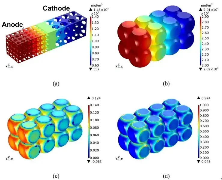
Figure 5. Simulated distributions at the end of 1C CC charging: (a) Li+ concentration in electrolyte, (b) solid-phase Li concentration in graphite, (c) strain in graphite particles, (d) stress in graphite particles[2]
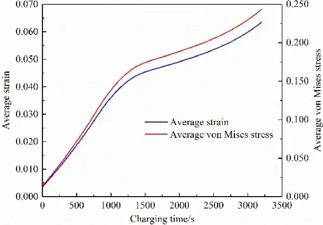
Figure 6. Average strain and average stress of the anode particles during charging[2]
The volume behavior during post-discharge rest (Area ‘B’ in Figure 3) is shown in Figure 7. A clear correlation exists: as the discharge rate decreases, both the magnitude of volume change during rest and the time required to stabilize also decrease.
This phenomenon mirrors the post-charge behavior and is similarly linked to internal polarization and inhomogeneous lithium concentration profiles established during discharge. Simulations confirm that higher discharge rates or thicker electrodes lead to greater lithium concentration gradients at the end of discharge (Figure 8), resulting in larger stress/strain gradients that relax during rest, causing measurable volume contraction.
Furthermore, the anomalous initial expansion observed at the start of discharge (Figure 3) becomes less pronounced at lower discharge rates. This suggests this expansion may also be related to thermal effects induced by high currents.
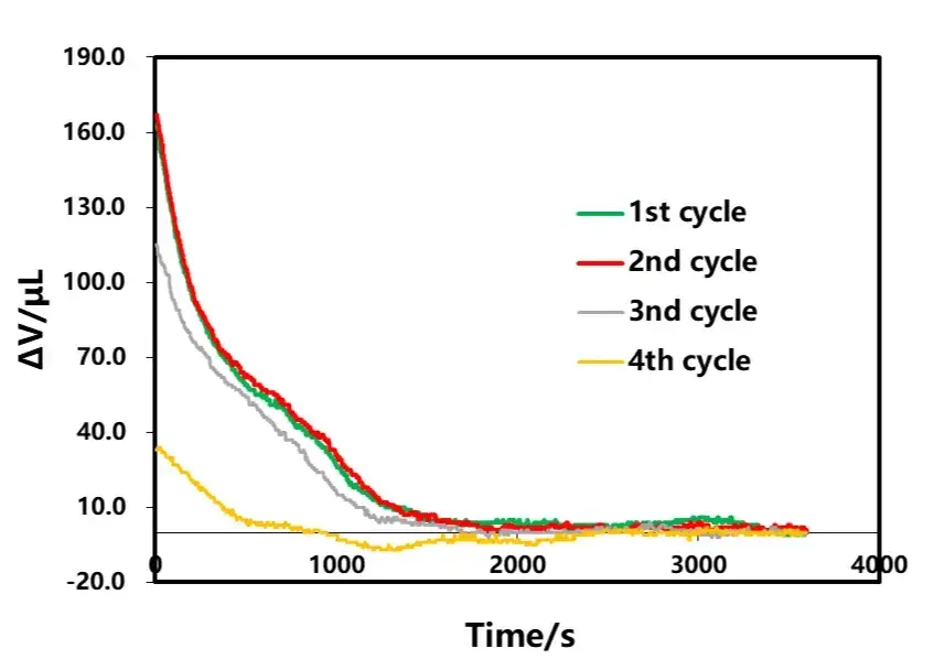
Figure 7. The effect of discharge current on volume change during the subsequent rest period.
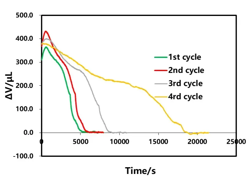
Figure 8. Discharge current effect on total volume and bounce volume
Similar to the simulation results of the constant current-constant voltage (CC-CV) charging process, during constant current (CC) discharging, lithium deintercalates from the negative electrode particles while simultaneously intercalating into the positive electrode particles as the discharge proceeds. Concurrently, the electrochemical potential drives the migration of lithium ions in the electrolyte from the negative electrode to the positive electrode. The lithium concentration within the negative electrode particles decreases, whereas it increases within the positive electrode particles.
Similarly, along the electrode thickness direction, an inhomogeneous distribution of lithium concentration exists. The magnitude of this concentration gradient is related to both the electrode thickness and the discharge rate. As shown in Figure 11, at the end of discharge, the lithium concentration distribution is relatively uniform when the electrode is thin or the discharge rate is low. However, pronounced concentration gradients emerge with increased electrode thickness or higher discharge rates. Specifically for the positive electrode, particles near the separator exhibit a higher lithium concentration compared to those near the current collector.
Consequently, as the discharge rate decreases, the internal lithium concentration gradient within the cell diminishes. This leads to a reduction in the stress and strain induced by concentration differences. As a result, the magnitude of volume change during the subsequent rest period becomes smaller, and the time required for the volume to stabilize is shortened.
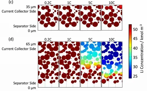
Figure 9. Distribution of lithium concentration in the solid phase of the particles at the end of discharge[3]
This study utilized the in-situ GVM2200 system to monitor the volume expansion behavior of Lithium Cobalt Oxide(LCO)/Graphite cells at different charge discharge rates. The findings reveal that volume changes during cycling and rest are influenced not only by lithium (de)intercalation but also by internal polarization, inhomogeneous lithium distribution, and associated thermal effects.
A key practical insight is that implementing a CV charge phase with a low cutoff current (e.g., <0.1C) can effectively homogenize the cell’s internal state before rest, minimizing post-charge volume relaxation. Conversely, since discharge often occurs at higher rates, a sufficient rest period should be allocated post-discharge to allow the cell to reach a stable state before subsequent testing or characterization.
[1] Anna Tomaszewska, Zhengyu Chu, Xuning Feng, et al.Lithium-ion battery fast charging: A review,eTransportation, 1 (2019) 100011.
[2] Factors affecting stress in anode particles during charging process of lithium ion battery, Journal of Energy Storage, 43(2021)103214.
[3] Hideki Kikukawa, Kohei Honkura, Michihisa Koyama.Influence of inter-particle resistance between active materials on the discharge characteristics of the positive electrode of lithium ion batteries, Electrochimica Acta, 278(2018)385-395.
Volume expansion is the measurable dimensional change a battery cell undergoes during charging, discharging, and rest, driven by three coupled mechanisms: electrode lithiation/delithiation (graphite anodes swell as lithium ions intercalate into the layered structure), gas evolution from electrolyte decomposition or side reactions, and mechanical stress relaxation within electrode particles and the jelly-roll or stack structure. In graphite anodes specifically, volume tracks State of Charge (SOC) almost linearly during CC charging, since each increment of lithium insertion produces a proportional lattice expansion. For pack and module designers, quantifying this expansion is critical because it directly determines the mechanical clearance, fixture pressure, and swelling allowance that must be engineered into a cell’s housing — undersized clearance can lead to case deformation, separator compression, or accelerated degradation over cycle life.
Yes — this is one of the more counterintuitive findings from in-situ monitoring. Cell volume continues to change well into the rest period immediately following charge or discharge, a phenomenon this study terms volume relaxation. The magnitude and duration depend heavily on how the preceding charge step ended: cycles that used a CC-only protocol with no constant-voltage (CV) tail, cut off at a relatively high 1C current, showed significant volume contraction that took approximately 1500 seconds (about 25 minutes) to fully stabilize during the one-hour rest window. By contrast, cycles that included a CV phase tapering current below 0.1C showed most of that same contraction happening during the CV step itself, leaving only minimal additional change once rest began. This means the “stable” voltage reading at rest onset does not necessarily correspond to a mechanically stable cell.
Charge discharge rate governs how uniformly lithium ions distribute through the electrode during the (de)intercalation process. At higher C-rates, lithium transport through the electrolyte and solid-state diffusion within particles cannot keep pace with the applied current, producing steeper concentration gradients — particles near the separator lithiate or delithiate faster than those near the current collector. These gradients translate directly into non-uniform stress and strain fields (confirmed by the electrochemical-mechanical modeling in Section 3.3), which is what drives the larger, slower-resolving volume changes observed during rest after high-rate cycles. Practically, this means fast-charging protocols and high-rate discharge applications (e.g. power tools, EV acceleration events) should budget longer rest or buffer time in test and pack-design protocols to let this relaxation complete before the next electrical or mechanical characterization step.
A: CC-only (constant current) charging terminates abruptly once the cutoff voltage is reached, leaving the cell with a high internal polarization state and a pronounced lithium concentration gradient across the electrode thickness — this requires a substantial rest period, 30 minutes or more in this dataset, before stress and strain fully relax and the cell reaches mechanical steady state. CC-CV charging adds a constant-voltage hold once cutoff voltage is reached, during which current naturally tapers to a low threshold (below 0.1C in this study). That tapering current effectively “irons out” the concentration gradient before the cell enters rest, so post-charge volume relaxation is minimal and fast. For test protocols where subsequent characterization (impedance, capacity, or dimensional measurement) needs a mechanically stable baseline, CC-CV with a low cutoff current is the more reliable choice; CC-only protocols should be paired with an extended rest window to avoid measuring a cell that is still relaxing.
A: Volume expansion during rest is measured using in-situ (in place, without removing the cell from the test fixture) volume or thickness monitoring instruments that continuously log dimensional change alongside voltage and current throughout charge, discharge, and rest — this is essential because, as this study shows, meaningful volume change continues well after the electrical cycle step ends. The data in this article was generated using IEST’s GVM2200 In-situ Gassing Volume Monitor, which combines real-time volume tracking with precise oil-bath temperature control from 20°C to 80°C, allowing researchers to isolate rate-dependent and temperature-dependent volume behavior under controlled, repeatable conditions rather than relying on post-hoc thickness spot-checks.
