-
iestinstrument
The Effects of Coating On the Separator Ionic Conductivity
1. Preface
As one of the crucial components of lithium-ion batteries, the separator directly affects key performance indicators such as current, capacity, and cycle life [1]. The separator should possess the following characteristics to meet battery requirements: (1) excellent wettability with electrolyte and ion permeability; (2) outstanding thermal stability to prevent short circuits caused by high-temperature shrinkage; (3) electronic insulation and electrochemical stability; (4) chemical stability, not reacting with the electrode or electrolyte; (5) high mechanical strength to withstand tension and deformation during the manufacturing process; (6) appropriate thickness, pore size, and porosity to optimize electrolyte ion transport while balancing mechanical strength and internal resistance. This paper will evaluate the impact of the coating on the separator ionic conductivity by testing the ionic conductivity of the base film and the coated separators prepared using different coating processes.
Microporous polyolefin separators, exemplified by polyethylene (PE) and polypropylene (PP), have become the most widely used separators in lithium-ion batteries due to their excellent mechanical properties, electrochemical stability, thermal stability, and low cost. However, despite their widespread use, polyolefin separators have several shortcomings, such as susceptibility to thermal shrinkage at high temperatures, low porosity, and poor electrolyte affinity, all of which can significantly impact battery performance. Currently, traditional polyolefin separators are often modified through methods such as grafting, coating, and the development of new materials and processing techniques[2].
Coating modification is a method of coating organic polymers or inorganic ceramic particles onto a polyolefin diaphragm or new material diaphragm as a support base film. Coating techniques generally include polymer coating, inorganic ceramic coating and organic/inorganic hybrid coating. The introduction of coatings in diaphragms has three main functions: 1) to enhance the liquid absorption and retention of the diaphragm to extend the cycle life of the battery; 2) to enhance the diaphragm’s high-temperature resistance or flame retardancy and improve the mechanical properties; and 3) to increase the function of the diaphragm’s closed pores to improve safety[3]. Coating the diaphragm further improves the mechanical and thermal properties of the diaphragm, but it is important to ensure that the coating porosity allows for ionic conduction. After the diaphragm is coated, it is important to confirm that the diaphragm performs as expected. In this paper, the effect of coatings on the Separator ionic conductivity performance will be characterized by testing the ionic conductivity of base films as well as coated Separators prepared by different coating processes.
2. Test Conditions & Methods
2.1 Test Equipment
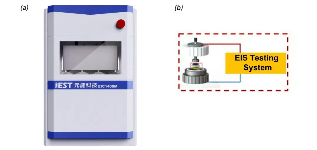
The self-developed multi-channel ionic conductivity testing system (EIC1400M) by IEST, as shown in Figure 1, was used. This equipment includes four battery assembly fixtures (Figure 1(b)) and can perform rapid four-channel electrochemical impedance spectroscopy tests. The pressure range is 0-20 Kg, and the frequency range is 100 KHz to 0.01 Hz.
Figure 1. (a) Multi-channel Ionic Conductivity Testing System: Equipment Overview; (b) Battery Assembly Fixtures
2.2 Test Samples
Base film A and separators B, C, and D prepared using different coating modification processes.
2.3 Test Procedure & Separator Ionic Conductivity Calculation Method
In the glove box, place the corresponding number of separators into the fixtures and add electrolyte. Place the assembled fixtures into the equipment and apply a 5 kg force. Initiate the experiment via software and after the set dwell time, automatically test the electrochemical impedance spectroscopy (EIS) of the four channels. The testing frequency ranges from 100,000 to 100 Hz. Perform assembly and testing for separators with 1 to 4 layers respectively, obtaining corresponding EIS curves. Fit these curves to establish a baseline, with the intersection of the fitting line and the X-axis representing the impedance Rs for the n-layer separator, as shown in Figure 2(a). Plotting the number of layers on the X-axis and the impedance value per layer on the Y-axis, perform linear regression on the data to obtain the slope, which represents the ionic impedance R of a single-layer separator, as depicted in Figure 2(b).
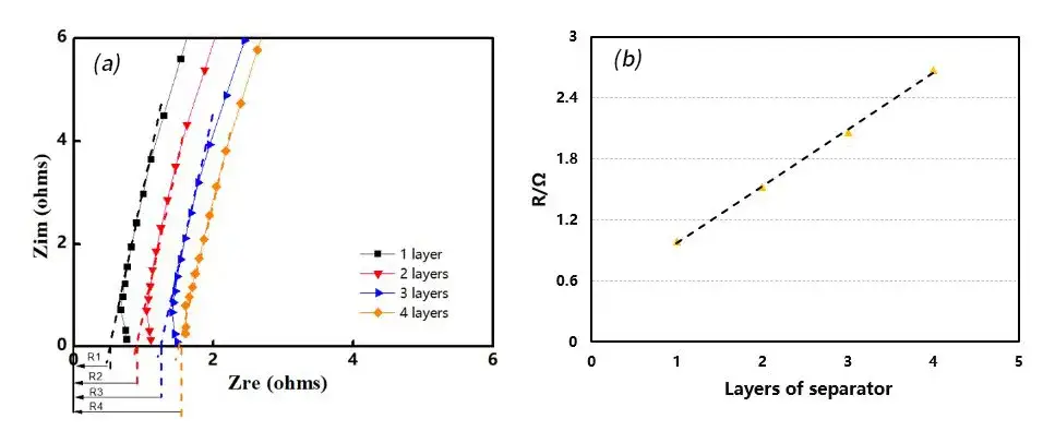
Figure 2. EIS Impedance Spectra of Different Separator Layer Numbers (a); R-Value Fitting Graph (b)
Substituting the obtained ionic impedance R into Formula 1 allows calculation of the separator ionic conductivity.
σ=d /( R * S)(1)
Where σ is the ionic conductivity, d is the thickness of the separator, R is the ionic resistance, and S is the effective surface area of the separator.
3. Data Analysis
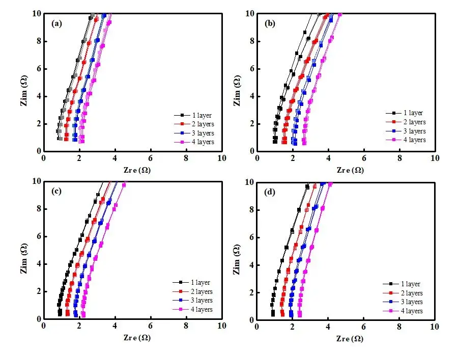
Figure 3. EIS Spectra of Separators with Different Coating Processes: Base Film A (a); Coated Separator B (b); Coated Separator C (c); Coated Separator D (d)
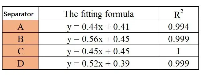
Figure 3 displays the EIS impedance spectra obtained from different separators. The data indicate that as the number of separator layers increases, the impedance values also increase. Using the obtained EIS as a baseline, linear regression was performed to determine the intersection values with the X-axis, as shown in Table 1, providing impedance values R1, R2, R3, and R4 for separators with 1 to 4 layers. Linear regression was then performed with the number of layers on the X-axis and R1, R2, R3, R4 on the Y-axis, as illustrated in Figure 4. The linear regression results are listed in Table 2. Through regression analysis, the ionic resistances R for the ABCD separators were determined to be 0.44 Ω, 0.56 Ω, 0.45 Ω, and 0.52 Ω, respectively. The data indicate that the coated separators have higher resistance than the base film, suggesting that increasing separator thickness enlarges the pathway for lithium-ion transport, thereby increasing impedance. Substituting R values into Formula (1) and calculating accordingly yields the corresponding ionic conductivities of the separators, as listed in Table 1: Separator C (0.00189 S/cm) > Separator B (0.00169 S/cm) > Separator D (0.00145 S/cm) > Separator A (0.00112 S/cm).
Table 1. Fitted Impedance Values and Ionic Conductivity Values of Separators with Different Numbers of Layers
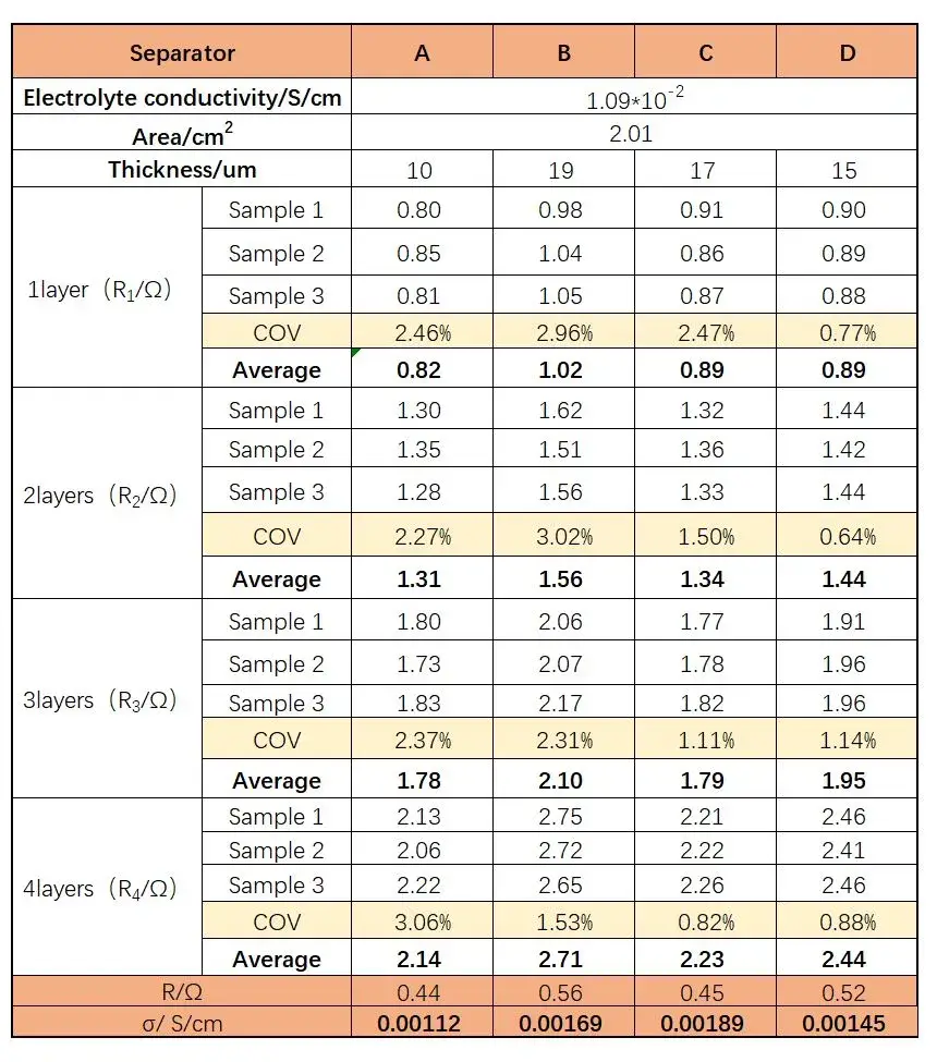
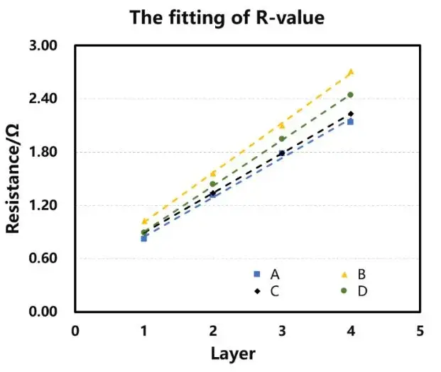
Figure 4. Linear regression graphs of different separators
Table 2. Linear Regression Equations and Coefficients of Determination for Different Separators
The separator ionic conductivity reflects the ease of lithium ion transport within them. By comparing the data, it is evident that the coated separators B, C, and D exhibit significantly higher conductivity than the base film A, increasing by 50.9%, 68.7%, and 29.4%, respectively. This indicates that coating modification provides additional pathways for lithium-ion transport, facilitating improved internal battery ion transport.
The separator ionic conductivity is influenced by microstructural parameters such as pore size, porosity (ε), and tortuosity (τ) of the separator material. Porosity is the ratio of pore volume to total volume, and an appropriately uniform porosity helps prevent local electrode polarization and lithium dendrite formation. Excessive porosity can reduce mechanical strength and increase thermal shrinkage, while low porosity can decrease liquid retention capacity and elongate the migration path of lithium ions. Tortuosity is the ratio of the actual ion migration distance to the separator thickness, and appropriate tortuosity helps reduce internal resistance in batteries, enabling rapid ion transport. Excessive tortuosity, however, can increase internal resistance and potentially induce lithium dendrite growth, leading to separator puncture. For instance, high porosity and large surface area-to-volume ratio can retain more liquid electrolyte and provide effective conduction pathways, while interconnected pores reduce ion transport tortuosity, facilitating efficient diffusion of Li+ through the separator.
When a coating is applied to the surface of a separator, it increases the thickness and consequently the path length for lithium ions to traverse through the separator. This can potentially alter the pore structure of the separator, affecting porosity and pore size distribution, which in turn impacts ion transport efficiency. Coatings may also alter the wettability and affinity of the separator, affecting the electrolyte’s absorption and retention capabilities, thereby influencing ion transport. However, coatings can enhance the mechanical strength and thermal stability of the separator, thereby improving safety.
4. Conclusion
This study utilized the self-developed multi-channel separator ionic conductivity testing system by IEST to measure the separator ionic conductivity with different coating processes. The sample testing showed good consistency and enabled clear comparisons between different coating techniques. By measuring the separator ionic conductivity, we can assess the ease of lithium-ion migration through the separator and verify whether the separator meets expected performance criteria. In addition to evaluating the effectiveness of different coating techniques, ionic conductivity testing can also be used to study the impact of electrolyte types and separator materials on the separator ionic conduction properties.
5. References
[1] Huang Xuejie. Progress in lithium-ion batteries and related materials [J]. China Materials Progress, 2010, 29 (8): 46-52.
[2] Li Jiaxing, Li Feng. Research progress in surface modification technology of polyolefin lithium battery separators [J]. Information Recording Materials, 2021, 22 (4): 3-8.
[3] CHOI J A, SA H K, KIM D W. Enhancement of thermal stability and cycling performance in lithium-ion cells through the use of ceramic-coated separators [J], Journal of Power Sources, 2010 (195): 6192-6196.
Subscribe Us
Contact Us
If you are interested in our products and want to know more details, please leave a message here, we will reply you as soon as we can.


