

DCIR (Direct Current Internal Resistance) is the total internal resistance of a lithium-ion battery, calculated using Ohm’s Law from the voltage response to a applied current pulse: \(R = \Delta V / \Delta I\). DCIR measurement quantifies a battery’s ohmic resistance and polarization resistance in a single test, making it the most widely used method for evaluating power capability, state of health (SOH), and production consistency across the battery lifecycle — from R&D through manufacturing and field deployment. Standard DCIR test procedures are defined in IEC 61960, GB/T 31486, and the USABC HPPC manual, each specifying different pulse durations and application scopes.
Direct Current Internal Resistance (DCIR) measurement refers to the process of applying a direct current step signal to a battery and calculating the resulting resistance from Ohm’s Law based on the measured voltage change. It represents the total internal impedance of a battery, encompassing both ohmic resistance and polarization resistance. As a core component of new energy vehicles, energy storage systems, and consumer electronics, battery performance and safety have always been key concerns in the industry. Internal resistance is one of the most commonly used and intuitive performance parameters in battery testing. It is closely related to a battery’s power characteristics and energy efficiency, and provides critical references for lifespan prediction and safety assessment.
This article demonstrates how to conduct internal resistance testing using IEST’s high-precision charge-discharge equipment in accordance with the IEC 61960 international standard, and walks through the actual testing process via software configuration steps.
DCIR testing is a core evaluation method that spans the entire battery lifecycle — from laboratory development and production line screening to end-use monitoring — because it simultaneously reflects power capability, aging state, and internal defect status.
State of Health (SOH) is defined as the ratio of a battery’s current capacity or power capability to its rated value at beginning of life, expressed as a percentage. The gradual increase of internal resistance is a direct quantitative indicator of battery aging: it reflects internal degradation such as loss of active material, electrolyte decomposition, and SEI layer growth. By periodically monitoring these resistance changes through DCIR measurement, engineers can accurately assess battery SOH and predict remaining useful life, much like how tracking blood pressure reveals cardiovascular health trends.
Internal resistance directly determines the battery’s voltage drop under high current (\(V_{drop} = I \times R\)). A lower internal resistance means less voltage sag, enabling stronger acceleration, faster charging, and reliable high-power output. DCIR is therefore a key metric for evaluating whether a battery cell can meet the peak power demands of applications such as electric vehicles and power tools.
Thermal runaway refers to an uncontrolled self-heating process triggered when internal heat generation exceeds the battery’s ability to dissipate it, potentially leading to fire or explosion. According to Joule’s Law (Q = I²Rt), abnormal internal resistance leads to excessive heat generation, increasing thermal runaway risk. Internal resistance testing can effectively screen out cells with internal defects such as micro-shorts, poor welds, or electrolyte dry-out, serving as a critical non-destructive safety inspection before batteries enter service.
A Battery Management System (BMS) is the electronic control unit responsible for monitoring, protecting, and optimizing battery pack operation, including SOC estimation, power limit enforcement, and cell balancing. An accurate internal resistance value from DCIR measurement is essential for the BMS to make correct decisions. It is crucial for precise State of Charge (SOC) estimation, real-time calculation of charge/discharge power limits, and implementing effective cell balancing strategies. Inconsistent internal resistance within a pack can severely compromise overall performance and lifespan.
On the production line, DCIR testing serves as a 100% inspection tool. It quickly identifies manufacturing flaws such as poor tab welding or insufficient electrolyte wetting. More importantly, DCIR measurement is the primary method for grading and matching cells with consistent internal resistance — the cornerstone of building high-performance, long-life battery packs.
DCIR measurement relies on the current pulse method: a defined current pulse is applied to the battery, the instantaneous voltage response is captured at high speed, and internal resistance is calculated from the ratio of voltage change to current change.
Apply a constant current pulse to the battery.
Record the instantaneous change in battery voltage.
Calculate internal resistance using the formula:
\[ R = \Delta V / \Delta I \]
Where:
\(\Delta V\) = Voltage difference before and after the current pulse
\(\Delta I\) = Magnitude of the pulse current
💡 Expert Tip:
DCIR measurement accuracy is fundamentally limited by the instrument’s sampling rate. General-purpose battery cyclers without dedicated high-speed sampling channels miss the instantaneous IR drop at the moment of current application, systematically underestimating internal resistance. The IEST ERT Series achieves 100 Hz high-speed sampling, capturing millisecond-level voltage transitions for true DCIR accuracy — a requirement not met by general-purpose cyclers.
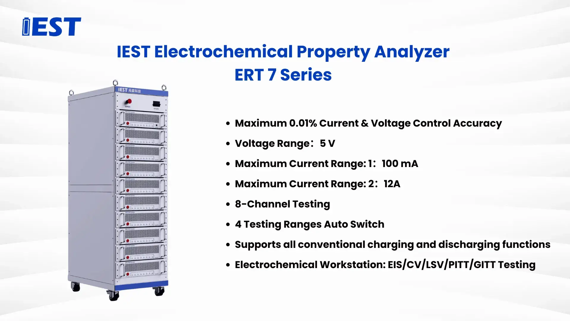
The IEST ERT/ECT Series achieves voltage and current measurement accuracy up to 0.01% and supports 100 Hz high-speed sampling. This enables precise control of pulse signals and efficient, reliable acquisition of the millisecond-level voltage data on which accurate DCIR calculation depends.
DCIR measurement must be performed under a defined standard to ensure that results are comparable across laboratories, instruments, and time points. Different standards — IEC, GB/T, and USABC — vary in pulse duration, test conditions, and application focus due to regional regulatory requirements and target application fields. Understanding these differences ensures test results are comparable and reproducible, and is the foundation for meeting specific market access requirements or customer technical specifications.
The table below compares the core stipulations of three widely used standards. Notably, the IEC 61960 standard employs both a primary 10-second pulse and a shorter 1-second pulse — a dual-pulse methodology that separates ohmic resistance and polarization resistance components that manifest over different timescales, providing richer data for in-depth performance analysis.
Table 1: Comparison of Key International Standards for DCIR Testing of Lithium-ion Batteries.
| Standard | Primary Scope / Application Field | Key Pulse Duration | Core Methodology & Purpose |
|---|---|---|---|
| IEC 61960 | Portable Electronics (International Benchmark) | 10s (Long) & 1s (Short) | Constant current pulse method. Uses two pulses to separate ohmic and polarization resistance for basic performance evaluation. |
| GB/T 31486 | EV Power Batteries (China Market Access) | Typically 10s | HPPC or constant current pulse. Mandatory for safety & performance certification, with a strong focus on power capability. |
| USABC Manual | EV/HEV Traction Batteries (North America) | 10s (within HPPC profile) | Hybrid Pulse Power Characterization (HPPC). Assesses peak power, available energy, and thermal management needs comprehensively. |
The practical distinction matters for equipment selection and interpretation: ACIR values are generally lower and faster to measure, making them suitable for high-throughput production screening at 1 kHz, while DCIR values better represent real-world power performance under sustained load because polarization effects only fully develop over one to ten seconds. Batteries with similar ACIR readings can show meaningfully different DCIR results if polarization resistance differs — which is why power-critical applications such as EV traction batteries specify DCIR, not ACIR, as the qualifying test.
The following illustrates the standard step sequence for IEC 61960 DCIR testing on the IEST ECT/ERT Series, consisting of three sequential phases that together capture both long-timescale and short-timescale resistance components.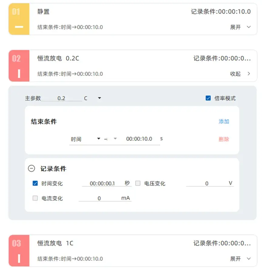
Figure 1. IEC 61960 DCIR test sequence measured by IEST ECT & ERT Series products, demonstrating the rest–10s pulse–1s pulse step configuration.
Purpose: Ensure the battery reaches a stable open-circuit voltage (OCV) state.
Function: Eliminate electrochemical disturbances from previous charge or discharge operations before the DCIR measurement begins.
Apply a constant current pulse at 0.2C rate for 10 seconds.
Record the instantaneous voltage drop (IR drop) and its subsequent gradual stabilization during the pulse.
This 10-second pulse is the primary data source for DCIR calculation per IEC 61960.
Apply a shorter 1-second pulse at the same 0.2C rate to capture the faster voltage response component.
The 1-second measurement isolates the ohmic resistance component from the slower polarization contribution captured in the 10-second pulse.
Comparing both results enables a more complete internal resistance model.

Figure 2. DCIR calculation and export performed automatically by IEST Analyzer software, demonstrating direct $R = \Delta V/\Delta I$ output from pulse test data.
The IEST ERT/ECT Series DCIR tester is designed to address the core accuracy, flexibility, and safety requirements of DCIR measurement across R&D, certification, and production quality control environments.
Voltage measurement accuracy to microvolt level, ensuring capture of the instantaneous IR drop at the moment of current pulse application.
100 Hz high-speed sampling rate and stable current control for accurate pulse delivery and reliable DCIR calculation.
Supports rate-based modes (e.g., 0.2C, 0.5C), enabling DCIR tester configuration for batteries across a wide capacity range without manual current recalculation.
Users can quickly configure test steps based on IEC 61960, GB/T 31486, or custom internal specifications, and save step templates for repeated use across batches.
Automatically calculates battery internal resistance, reducing manual analysis errors.
Supports data export for further modeling and analysis.
Fully compatible with IEC 61960, GB/T 31486, and USABC HPPC test methodologies.
Suitable for various applications including research, certification, and quality inspection.
Built-in overvoltage, overcurrent, and overtemperature protection on all channels.
Ensures safety for both the test instrument and the battery under test during high-current pulse operation.
Missed IR drops from low sampling rates lead to underestimated internal resistance. The IEST ERT/ECT Series delivers 100 Hz high-speed sampling with 0.01% voltage and current accuracy, supporting IEC 61960, GB/T 31486, and USABC HPPC DCIR test configurations out of the box.
IEST ERT/ECT Series DCIR testing solutions are deployed across multiple application environments:
Power Battery R&D: Analyze the impact of different cathode and anode material systems on internal resistance at the cell level.
Production Quality Inspection: Perform 100% DCIR screening to identify cells with abnormal internal resistance and improve pack-level consistency.
Energy Storage System Validation: Monitor internal resistance changes in large-format storage batteries over cycling to detect aging trends before failures occur.
Research Experiments: Combine DCIR measurement with EIS, cyclic voltammetry (CV), and rate capability tests to build comprehensive electrochemical models.
In practical terms, DCIR functions as a “cardiovascular health check” for batteries:
The internal resistance value is akin to blood vessel patency (resistance). Low resistance means smooth blood (current) flow and strong pumping capacity of the heart (battery).
Changes in internal resistance reflect aging and pathological changes (degradation and defects).
By tracking DCIR, engineers can assess power performance, quantify SOH, and identify safety risks — then act on that information through BMS management strategies or cell replacement decisions.
Throughout the entire battery lifecycle — from electrode material R&D and cell formation through production-line grading, pack assembly, and field monitoring — DCIR testing remains the most operationally practical and data-efficient method for evaluating battery performance, health, and safety. Accurate DCIR measurement requires a dedicated DCIR tester with millisecond-level sampling capability, calibrated current pulse control, and compliance with the applicable test standard (IEC 61960, GB/T 31486, or USABC). These requirements are the baseline for producing resistance data that is reproducible across instruments, operators, and laboratories.
To learn more about high-precision DCIR testing solutions, contact IEST Instrument for technical consultation and equipment specifications.
Direct Current Internal Resistance (DCIR) is a key performance metric that represents a battery’s total internal opposition to current flow. Measured by applying a current pulse and calculating resistance via Ohm’s Law (R = ΔV/ΔI), and it directly reflects a battery’s power capability, state of health, and safety.
A rising DCIR is a primary indicator of battery aging and potential failure. Increased resistance leads to more heat generation (Q=I²Rt), raising thermal runaway risk. Monitoring DCIR growth over time is a direct method to quantify SOH degradation and identify safety hazards before they become critical.
ACIR (Alternating Current Internal Resistance) uses a 1 kHz AC signal and mainly captures ohmic resistance, while DCIR uses a 1–10 second DC current pulse and captures both ohmic and polarization resistance. ACIR is faster for production-line screening; DCIR better represents real-world power performance under sustained load. Equipment such as the IEST ERT/ECT Series supports both test types on the same platform.
A standard DCIR test procedure, such as IEC 61960, involves resting the battery to a stable open-circuit voltage, applying a constant-current discharge pulse (for example, 10 seconds at 0.2C), and measuring the instantaneous voltage drop. High-precision equipment, such as IEST’s ERT/ECT Series testers, automates this process, controls pulse accuracy, and calculates DCIR directly from the recorded data.
Accurate DCIR measurement requires a dedicated DCIR tester with high-speed, high-precision voltage and current sampling — to capture millisecond-level pulses — plus programmable pulse control. The IEST ERT/ECT Series meets these needs with 100 Hz sampling and 0.01% accuracy, supporting reliable, standards-compliant testing for R&D and quality control.
