

Lithium-ion batteries experience structural swelling and contraction during delithiation and lithium intercalation. For anode materials — whether intercalated lithium in graphite or alloyed lithium in silicon-based anodes — the common feature is a clear volume expansion on lithium insertion and a clear shrinkage on lithium extraction, consistent with conventional expectations. During pouch-cell swelling testing, however, cells built with some cathode systems — particularly high-nickel ternary (NCM) materials — shift from expansion to contraction at the end of charging, then expand briefly before shrinking again at the start of discharge. This is the “M”-type swelling behavior, and it is most likely caused by the cathode electrode, which is why cathode-side swelling behavior deserves closer attention.
Two ternary cathode materials with different nickel contents, NCM111 and NCM622, were assembled into button-type full batteries (conventional graphite anodes in both cases) to measure swelling thickness through charge-discharge cycling. Testing used IEST silicon-based anode swelling in-situ rapid screening system (RSS1400, Figure 1(a)), with swelling thickness results shown in Figure 1(b).
For the button-type full battery using NCM111 cathode material, thickness expanded monotonically during charging and contracted monotonically during discharge. For the higher-nickel NCM622 cathode material, swelling and contraction were non-monotonic: the cell expanded during most of charging but showed contraction in the high-voltage region near the end of charge. This behavior reversed during discharge — expansion occurred first, then contraction. Across three charge-discharge cycles, NCM622 consistently reproduced this “M”-type swelling pattern, indicating the behavior is intrinsic to high-nickel cathode materials rather than a measurement artifact.
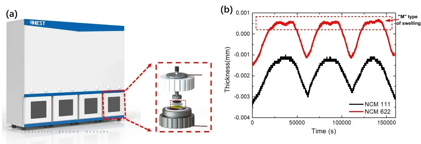
Figure 1.(a) Silicon-based anode swelling in-situ rapidscreening system (RSS1400); (b) NCM111 and NCM622 cathode materials assembled into a button-type full battery, and monitoring the swelling thickness change during three cycles of charge and discharge, Among them, NCM622 exhibits an “M” type of swelling behavior.
The NCM cathode electrode belongs to the α-NaFeO2 type crystal [1], and its specific crystal structure is shown in Figure 2, where the green is lithium-ion, the blue is transition element (TM) ions, and the red is oxygen ions. The layered units composed of oxygen ions and transition element ions are arranged longitudinally along the c-axis, while lithium-ion are alternately distributed between these layered units along the c-axis, forming a typical ABC-type stacked cubic stacking structure [1].
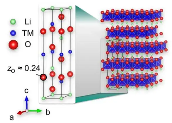
Figure 2. Schematic diagram of the crystal structure of layered LiNixCoyMnzO2[1].
F.B. Spingler et al.[2] studied swelling behavior across NCM cathode materials with different nickel contents, plus NCA cathode material, with results shown in Figure 3. As delithiation deepens in NCM111, the swelling curve is relatively flat at first — even showing a slight decline — before trending clearly upward; on discharge lithium intercalation, the curve shrinks noticeably at first, then flattens. As nickel content increases, cathode swelling decreases during delithiation and even contracts at the end of delithiation (the high-voltage region); this contraction is reversible on lithium insertion during discharge, as shown in detail in Figure 3(c) and (d).
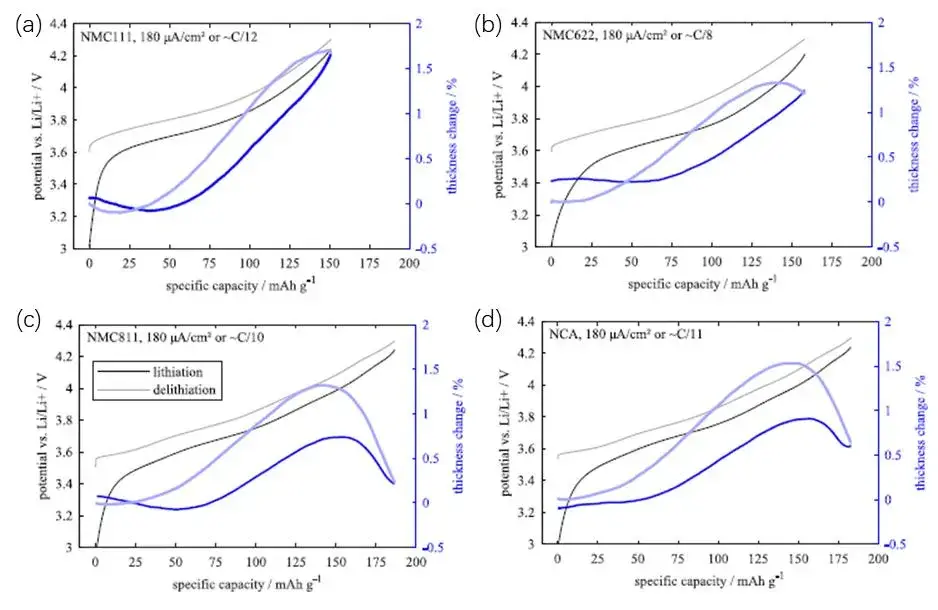
Figure 3. Variation of the swelling thickness of the ternary cathode with the gram capacity[2] (The upper limit cut-off voltage is 4.3V), where (a) is NCM111, (b) is NCM622, (c) is NCM811, (d) is NCA cathode.
| Cathode Material | Charging Swelling Behavior | High-Voltage Region (≈4.2–4.3V) | Full-Cell “M”-Type Swelling |
|---|---|---|---|
| NCM111 (low Ni) | Monotonic expansion | No contraction observed | No |
| NCM622 (mid-high Ni) | Expansion, then contraction near top of charge | Reversible contraction begins | Yes |
| NCM811 / NCA (high Ni) | Expansion, then more pronounced contraction | Contraction onset advances toward ≈4.0V | Yes (more pronounced) |
| LCO (no Ni) | Monotonic expansion | No contraction observed | No |
To explain this Ni-content-dependent swelling behavior, L.D. Biasi et al. [1] used in-situ XRD to study the 2θ angle shift of the 003 crystal plane for ternary cathode materials with different nickel contents (NCM111, NCM523, NCM622, NCM721, NCM811, and NCM851005) during charging, with results shown in Figure 4. As nickel content increases, the 003 crystal plane shifts to a higher angle under high voltage, indicating the 003 plane spacing shrinks significantly at high voltage.
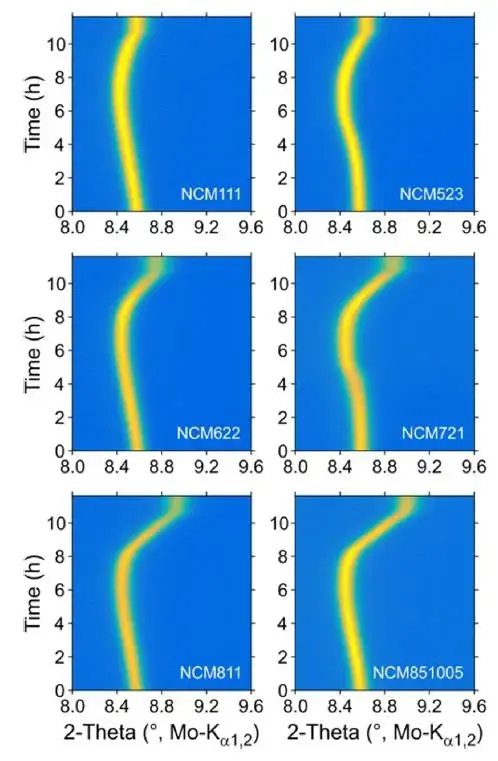
Figure 4. The change of the 2θ angle of the 003 crystal plane during charging of NCM cathode cells with different Ni contents under in-situ XRD test [1].
L.D. Biasi et al. [1] then analyzed how the a-axis and c-axis of the NCM crystal vary with voltage (Figure 5). During charging and delithiation, the a-axis contracts first, then flattens; the c-axis expands noticeably at first, then begins to shrink, and as nickel content increases, this second-half c-axis shrinkage becomes more pronounced and its onset voltage moves earlier.
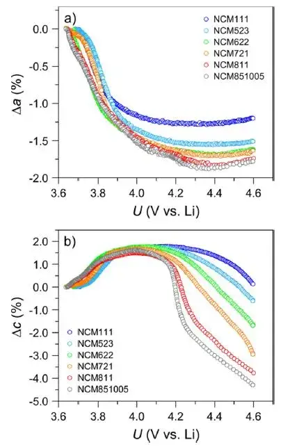
Figure 5. The relative spacing of the a-axis and c-axis with voltage during the charging and delithiation process of NCM cathode cells with different Ni contents [1].
The smaller a-axis spacing is generally attributed to oxidation of the transition metal (TM), while the larger c-axis spacing reflects increased Coulomb repulsion between NCM crystal layers after lithium-ion extraction. As delithiation deepens, the c-axis generates a large number of voids — especially in high-nickel ternary materials — eventually causing structural shrinkage (smaller spacing at high voltage). F.B. Spingler et al. [2] note that microscopic swelling accumulates into macroscopic reversible swelling, but microscopic shrinkage does not necessarily produce macroscopic shrinkage — it instead increases certain gaps within the electrode structure. The c-axis expansion and contraction are the main drivers of ternary material swelling and contraction during charging, and as nickel content rises, the c-axis shrinkage voltage advances from about 4.2V to about 4.0V (vs. Li). In a ternary-graphite full-cell system with a typical 3V–4.2V charge window, low-nickel ternary cells expand monotonically on charge and contract monotonically on discharge, while high-nickel ternary cells expand then contract on charge, and expand then contract on discharge — producing the “M”-shaped swelling curve.
Lithium cobalt oxide (LCO) also belongs to the α-NaFeO2-type crystal family. B. Rieger et al. [3] used in-situ XRD combined with a swelling test system to study LCO cathode swelling behavior during charging (Figure 6). As with NCM, the a-axis contracts during charging and delithiation (Figure 6(a)), while the c-axis shows clear swelling from increased Coulomb repulsion, ultimately producing macroscopic swelling of the LCO crystal. Across the full voltage range, LCO cathode material shows a monotonous swelling trend with no volume shrinkage at high voltage — consistent with low-nickel ternary behavior, since LCO contains no nickel.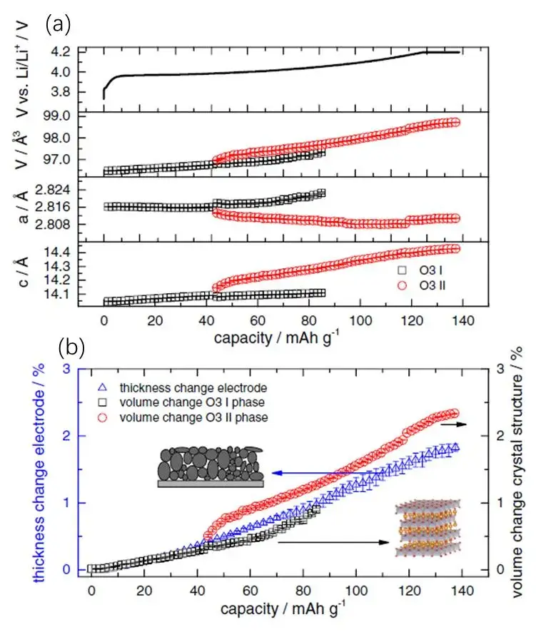
Figure 6. (a) When the O3 I phase changes to the O3 II phase, the a-axis, c-axis and unit cell volume change with the charging capacity; (b) During the charging process, the volume of the O3 I phase, the volume of the O3 II phase, and the thickness of the electrode sheet vary with the charging capacity.
In this paper, using IEST RSS1400 silicon-based anode swelling in-situ rapid screening system, swelling tests on ternary cathode electrodes showed that high-nickel ternary systems exhibit “M”-type swelling at high voltage — a behavior driven by three related mechanisms:
IEST RSS1400 in-situ rapid screening system monitors real-time swelling thickness across full charge-discharge cycles, distinguishing monotonic and “M”-type behavior across NCM, NCA, and silicon-based systems without disassembling the cell.
[1] L.D. Biasi, A.O. Kondrakov, H. Gebwein, T. Brezesinski, P. Hartmann and J. Janek, Between Scylla and Charybdis: Balancing Among Structural Stability and Energy Density of Layered NCM Cathode Materials for Advanced Lithium-ion Batteries. J. Phys. Chem. C 121 (2017) 26163–26171.
[2] F.B. Spingler, S. Kucher, R. Phillips, E. Moyassari and A. Jossen, Electrochemically Stable In Situ Dilatometry of NCM, NCA and Graphite Electrodes for Lithium-ion Cells Compared to XRD Measurements. J. Electrochem. Soc. 168 (2021) 040515.
[3] B. Rieger, S. Schlueter, S.V. Erhard and A. Jossen, Strain Propagation in Lithium-ion Batteries from the Crystal Structure to the Electrode Level. J. Electrochem. Soc. 163 (2016) A1595-A1606.
“M”-type swelling is a non-monotonic thickness pattern in which a high-nickel NCM cathode material expands through most of charging, contracts near the top-of-charge voltage (around 4.2V to 4.3V), then briefly re-expands before contracting again during discharge. It is an intrinsic property of high-nickel ternary cathode materials, not a testing artifact.
Low-nickel NCM cathode material, such as NCM111, expands monotonically during charging and contracts monotonically during discharge. High-nickel NCM cathode material, such as NCM622, expands during most of charging but contracts near the end of charge, then re-expands briefly before contracting during discharge — producing the “M”-type swelling curve.
Three related mechanisms drive “M”-type swelling: c-axis expansion from increased Coulomb repulsion during delithiation, late-stage c-axis contraction from void formation at high nickel content, and an earlier contraction-onset voltage as nickel content rises. Together, these produce contraction near the end of charge and reversible re-expansion at the start of discharge.
In-situ XRD records diffraction patterns from an NCM cathode material while it is being charged, tracking real-time shifts in the 2θ angle of the 003 crystal plane and changes in a-axis and c-axis lattice spacing. This shows that the a-axis contracts while the c-axis first expands then contracts, with the contraction becoming more pronounced and starting earlier as nickel content increases.
Under a 4.3V charge cutoff, NCM cathode materials show a-axis contraction alongside c-axis expansion through most of charging, with the c-axis beginning to contract in the high-voltage region. As nickel content increases, this c-axis contraction onset shifts from around 4.2V toward 4.0V (vs. Li).
Choosing a swelling test method for ternary cathode materials depends on whether reversible, cycle-resolved thickness data is needed alongside electrochemical cycling, rather than a single before-and-after measurement. IEST RSS1400 addresses this by providing continuous in-situ swelling monitoring across charge-discharge cycles for NCM, NCA, and silicon-based systems without cell disassembly.
