-
iestinstrument
Electrode Resistance Test Parameter Selection Basis
1. Preface
This paper proposes a more appropriate test parameter based on the specific test data of the electrode resistance, so as to ensure the accuracy and stability of the test data.
The evaluation of the coating uniformity of the cathode and anode electrodes is an important monitoring item in the battery production process. If the uniformity of the electrode sheets after coating or rolling is poor, it will significantly affect the performance consistency of the back-end cells. At present, the commonly used method to evaluate the coating uniformity of the electrode is mainly to monitor the thickness, quality and resistance, among the selection of test parameters for electrode resistance(membrane resistance), such as test pressure and pressure holding time, is extremely important to the stability of the measurement results.
Figure 1. Schematic diagram of electrode resistance test
2. Laboratory Equipment
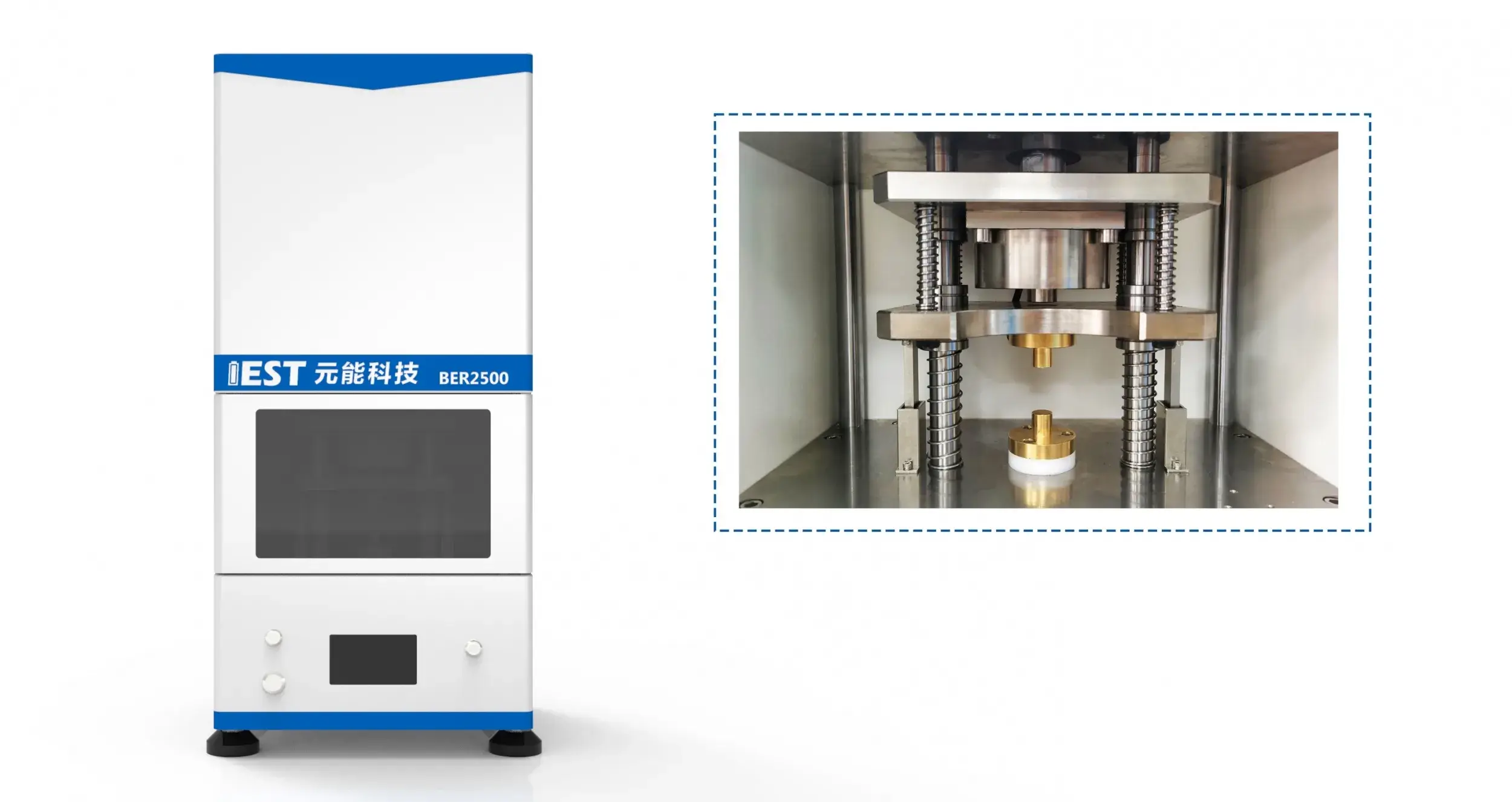
Equipment Model: BER2500 (IEST), electrode diameter 14mm. The equipment is shown in Figures 2(a) and 2(b).
Figure 2 (a) BER2500 appearance; (b) BER2500 structure diagram
3. Data Analysis
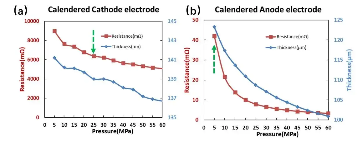
We carried out in-situ thickness and resistance tests on the cathode and anode electrodes after rolling under different pressures (5-60MPa), as shown in Figure 3. It can be seen from the figure that with the increase of the test pressure, the resistance of the cathode and anode electrodes decreases continuously, and the maximum thickness of the cathode electrode changes by about 4 μm, and the maximum thickness of the negative electrode changes by about 25 μm. During the test, it is necessary not to affect the state of the sample to be tested as much as possible, and at the same time, it is necessary to ensure that the test electrode is in close contact with the sample. Therefore, we recommend that the test pressure of the cathode electrode piece be 25MPa, and the anode electrode be selected as 5MPa.

Figure 3. Test results of resistance and thickness of cathode and anode electrodes under different pressure conditions
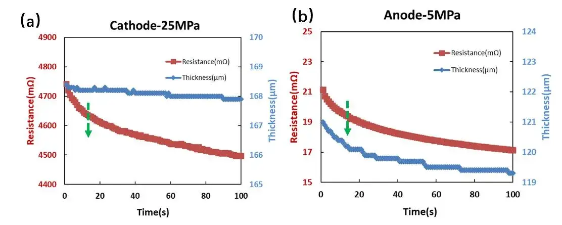
Next, we further explored the appropriate pressure holding time, and tested the resistance and thickness data of the cathode and anode electrodes under the same pressure for 100 seconds continuously, as shown in Figure 4. It can be seen from the figure that as the holding time increases, the resistance of the cathode and anode electrodes decreases continuously, and the maximum thickness of the cathode electrode varies by no more than 1 μm, and the maximum thickness of the anode electrode varies by about 1.5 μm. During the test, it is necessary to shorten the test time as much as possible, improve the test efficiency, and at the same time ensure the stability of the test data. Therefore, we recommend that the pressure holding time of the cathode and anode electrodes be selected as 15s.

Figure 4. Resistance and thickness test results under different holding time conditions for cathode and anode electrode
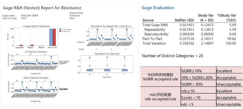
Adopting the test conditions as above, we choose 10 kinds of cathode electrodes to analyze the MSA of the device, because the electrodes are not reusable after each position is tested, so it belongs to the destructive test, we choose the nested GR&R study, and the results are shown in Figure 5, from which it can be seen that the device’s reproducibility and distinguishability are at an excellent level.

Figure 5. GR&R Analysis of Battery Electrode Resistance Tester
4. Summary
Through the exploration of the test parameters (pressure and holding time) of the electrode resistance, we recommend 25MPa for the cathode electrode, 5MPa for the anode electrode, and a holding time of 15s for both, the repeatability and distinguishability of the electrode resistance data obtained from the test under this condition reached an excellent level.
5. References
[1] Serena W. Peterson and Dean R. Wheeler, Direct Measurements of Effective Electronic Transport in Porous Li-Ion Electrodes. Journal of The Electrochemical Society, 161 (14) A2175-A2181 (2014).
[2] Hiroki Kondo et al. Influence of the Active Material on the Electronic Conductivity of the Positive Electrode in Lithium-Ion Batteries. Journal of The Electrochemical Society, 2019,166 (8) A1285-A1290
[3] B.G. Westphal et al. Influence of high intensive dry mixing and calendering on relative electrode resistivity determined via an advanced two point approach. Journal of Energy Storage 2017, 11, 76–85
Subscribe Us
Contact Us
If you are interested in our products and want to know more details, please leave a message here, we will reply you as soon as we can.


