

With the rapid development of new energy vehicles, consumers have increasingly higher demands for the charging time and driving range of electric vehicles (EVs). Battery fast charging technology has become a core competitive advantage for power battery companies participating in future market competition and is undergoing rapid iterative innovation. Clearly identifying the limitations of lithium-ion battery fast charging speed is beneficial for promoting innovation and development in battery technology. It can provide guidance and insights for the development of new materials, exploration of new processes, and optimization of battery design and systems — building on the broader framework established in reviews such as Tomaszewska et al.’s “Lithium-Ion Battery Fast Charging: A Review” (eTransportation, 2019), which this article’s analysis draws on and extends with original in-situ testing data.
The main factors that limit the fast charging performance of lithium-ion batteries are as follows: six interacting categories, summarized in the table below and examined in detail in the sections that follow.
| Limiting Factor | Primary Mechanism | Effect on Fast Charging | Typical Severity |
|---|---|---|---|
| 2.1 Material | Li+ transport resistance across 7 sequential steps: cathode diffusion → CEI → solvation → electrolyte migration → desolvation → SEI → anode diffusion |
Sets the theoretical ceiling on achievable rate before other factors even apply | High |
| 2.2 Temperature / SOC | Low temperature raises electrolyte viscosity and internal resistance; high SOC pushes anode potential toward the lithium plating threshold | Fast-charging voltage and safe current both shrink outside the optimal temperature/SOC window | High |
| 2.3 Charging Method | CC, CV, and pulse protocols each trade off speed, polarization, and material stress differently | Wrong protocol choice accelerates aging even at the same average C-rate | Medium |
| 2.4 Lithium Plating | Li+ arrives at the anode surface faster than it can intercalate, depositing as metallic lithium | Hard ceiling — plating triggers capacity fade, impedance rise, and short-circuit risk | High |
| 2.5 Manufacturing | Electrode particle size/porosity, separator thickness, and assembly consistency | Determines how close a cell can get to its material-level theoretical rate capability | Medium |
| 2.6 Safety Limits | Overcharge, over-discharge, and overheating protection thresholds | Caps current/voltage regardless of what the electrochemistry could otherwise tolerate | Low–Med |
When a lithium-ion battery is charging, Li⁺ is transferred from the positive electrode to the negative electrode through the electrolyte. Rather than one step, this transport path is a chain of seven sequential processes — a slow link anywhere in the chain becomes the rate-limiting step for the whole cell:
| Step | Li+ Transport Process |
|---|---|
| 1 | Diffusion of Li+ within the cathode (positive electrode) material |
| 2 | Diffusion of Li+ through the cathode/electrolyte interface (CEI) |
| 3 | Solvation of Li+ by solvent molecules at the CEI |
| 4 | Diffusion and migration of solvated Li+ through the bulk electrolyte |
| 5 | Desolvation of Li+ at the anode/electrolyte interface (SEI) |
| 6 | Li+ passage through the SEI layer into the anode |
| 7 | Solid-state diffusion of Li+ within the anode (negative electrode) material |
Because any one of these seven steps can become the bottleneck, positive and negative electrode materials, electrolytes, separators, and battery structures all affect fast charging performance — a set of challenges and opportunities that continues to drive fast-charging battery materials research.
Environmental temperature has a significant impact on the fast charging performance of lithium-ion batteries — and low- and high-temperature environments create opposite, but equally limiting, problems:
| Condition | What Happens Internally | Consequence for Fast Charging |
|---|---|---|
| Low temperature | Electrolyte viscosity rises, Li+ diffusion and ion conduction slow, internal resistance increases[3] | Charging speed drops; available capacity shrinks; highest lithium-plating risk (see Section 2.4) because slowed Li+ diffusion lets ions accumulate at the anode surface instead of intercalating |
| High temperature | Internal chemical reaction rates accelerate, which on its own would support faster charging | Heat dissipation becomes the constraint — poor thermal control risks overheating, swelling, and in extreme cases thermal runaway once the safety threshold is exceeded |
Because both extremes are limiting in different ways, fast charging requires an appropriate operating temperature window rather than simply “more heat = faster charging.” Some electric vehicle battery packs are equipped with heating or cooling systems to keep cells within this optimal range, and charging equipment should include over-temperature protection to prevent overheating.
Beyond in-use temperature, ambient conditions during manufacturing also set a ceiling on achievable fast-charging performance:
| Manufacturing Condition | Risk If Uncontrolled |
|---|---|
| High ambient humidity | Elevated internal moisture content, raising the risk of internal short circuits or unwanted redox reactions that degrade performance and life |
| High O2 or CO2 concentration | Reaction with internal battery chemicals, degrading performance and life — requires well-ventilated manufacturing environments |
The charging method used — constant current (CC), constant voltage (CV), pulse charging, or a multi-stage combination — also affects fast-charging performance, each with a distinct speed/stress trade-off:
| Method | How It Works | Advantage | Limitation |
|---|---|---|---|
| Constant Current (CC) | Maintains a fixed current intensity throughout charging | Simple control; fast at high rates | Terminal voltage rises as charging progresses, unsuitable for long-term charging; risk of overheating and overcharging |
| Constant Voltage (CV) | Maintains a fixed voltage, typically following a CC stage to the cut-off voltage, to even out Li+ concentration distribution | Suitable for extended charging; corrects uneven ion distribution | Current — and thus speed — decreases as charging progresses; greater delithiation/lithiation stress can damage internal materials. This CC-CV transition at elevated SOC is also where lithium plating risk peaks (Section 2.4) |
| Pulse Charging | Intermittent fast-charging bursts separated by short pauses | Pauses allow ion concentration to relax, easing polarization and internal resistance buildup | Benefit depends on pulse frequency, duty cycle, and cell design (see FAQ Q7) |
| Multi-Stage CC | Two or more sequential CC stages of decreasing current, followed by a CV stage | Larger current in the early stage (when anode potential is far from the plating threshold) speeds up charging while reducing heat, plating risk, and mechanical stress versus single-stage CC | More complex control algorithm and calibration than single-stage CC |
Lithium evolution, or lithium plating, refers to the process in which Li⁺ forms lithium metal on the surface of the negative electrode during fast charging, most commonly under the combined conditions of low temperature (Section 2.2) and high SOC during CC-CV charging (Section 2.3). Once triggered, plating sets off a chain of downstream consequences:
Table 6. The four-step consequence chain of lithium plating during fast charging.
In conclusion, lithium plating is an important factor affecting the fast-charging performance of lithium-ion batteries — and, as the consequence chain above shows, it is also the factor with the most severe worst-case outcome (internal short circuit and thermal runaway), which is why precisely locating the lithium plating window (Section 3) is a priority for fast-charging strategy development.
Manufacturing technology determines not only the structure and performance of the battery but also its safety and life. Three process-level variables have the most direct impact on fast-charging capability:
| Process Variable | Effect on Fast Charging |
|---|---|
| Electrode particle size, distribution & porosity | Smaller particles give a larger specific surface area and shorter Li+ transport path, increasing insertion/extraction speed |
| Separator thickness & porosity | A thin separator with appropriate porosity reduces internal resistance and improves Li+ transmission efficiency, while separator strength and thermal stability must still be maintained for safety |
| Cell assembly process | Structural design, component assembly, and uniformity of conductive-agent distribution affect overall performance and safety consistency across cells |
Improving fast-charging performance therefore requires optimizing electrode preparation, separator selection, battery structure, and assembly process together — which in turn requires advanced manufacturing equipment and fine process control to ensure battery consistency and reliability.
Fast charging technology must also work within safety limits — avoiding overheating, overcharging, and over-discharging — and these protective thresholds can themselves cap the current or voltage a charging protocol is allowed to use, independent of what the underlying electrochemistry could otherwise tolerate.
In general, there are many factors that limit the fast-charging performance of lithium-ion batteries, including materials, charging environment, charging methods, lithium deposition, manufacturing processes and safety factors. Among these, lithium plating is the factor with the least mature in-situ, non-destructive characterization method: material properties, environmental conditions, charging method, and manufacturing consistency can all be evaluated with established analytical techniques, but confirming whether and when lithium plating occurs during fast charging has traditionally required destructive cell disassembly. This gap is what the in-situ swelling analysis described in Section 3 is designed to close.
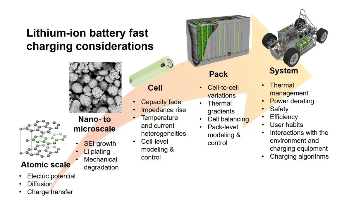
Figure 1. Factors affecting the fast charging of lithium-ion batteries at different levels[5]
Three methods are used to detect lithium plating during fast charging, each with different trade-offs between accuracy, sample damage, and quantitative rigor:
| Method | How It Works | Key Limitation |
|---|---|---|
| Cell Disassembly | Dismantle a fully charged cell and visually inspect the negative electrode for gray-white lithium deposits | Destructive (out-of-situ); only approximates the evolution rate/temperature, cannot resolve an accurate plating window |
| In-Situ Optical Imaging | Direct dynamic observation of Li+ deposition and growth morphology during charging | Requires special cell structure, has poor resolution, and cannot perform quantitative analysis |
| Three-Electrode Potential Detection | A reference electrode monitors negative-electrode potential; plating is inferred once potential drops below ~0V (vs Li+/Li) | Reference electrode selection and placement directly affect accuracy and reproducibility |
To solve the limitations of these traditional methods, IEST uses the self-developed in-situ swelling analyzer (SWE) to quantitatively evaluate the swelling thickness of the battery core at different charging rates. This determines the lithium plating voltage and SOC window at different charging rates without the resolution and quantification limits of optical imaging or the destructiveness of disassembly, providing a new method for R&D personnel to formulate fast charging strategies.
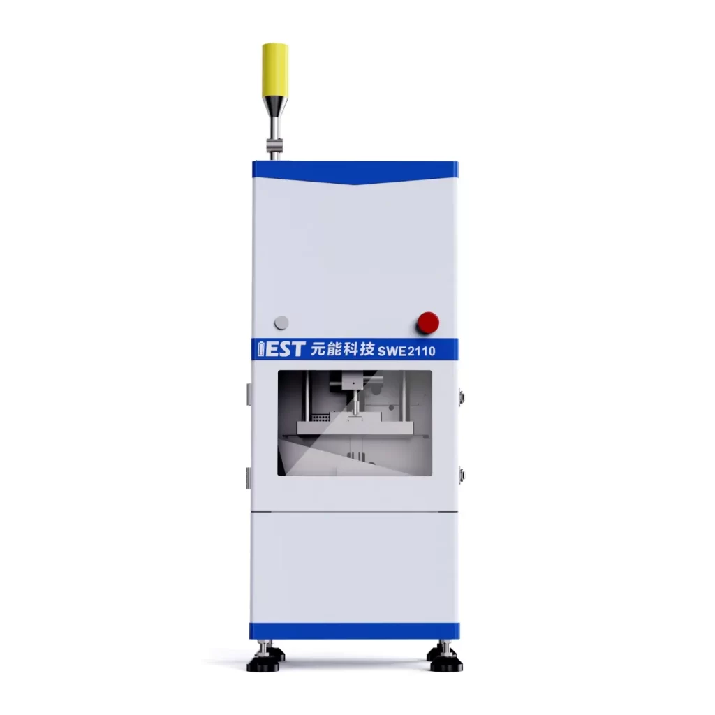
Figure 2. Schematic diagram of the IEST in-situ swelling analyzer (SWE)
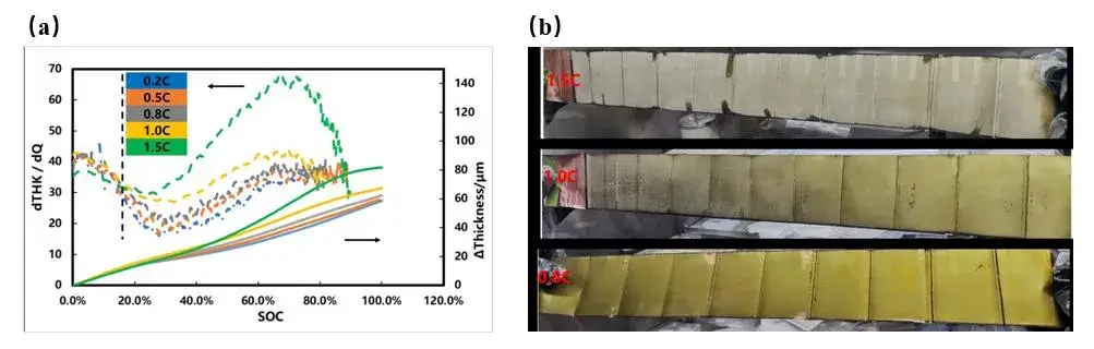
Figure 3. (a) Swelling thickness curves at different charging rates and (b) disassembled electrode after full charging, showing lithium plating onset
Different charging rates are used to charge the battery. It can be clearly seen from Figure 3(a) that the 1C and 1.5C rate swelling thickness curves, when charged to about 15% SOC, along with the other three rate swelling thickness curves, a “bifurcation” phenomenon began to occur. It is speculated that as the charging rate increases, the battery polarization increases, and lithium plating occurs on the surface of the negative electrode, which leads to an acceleration of the battery cell swelling rate. To verify whether there is lithium plating in the battery core, the fully charged battery core was disassembled to observe the negative electrode surface, as shown in Figure 3(b): when fully charged at a rate of 1.5C, the entire surface of the negative electrode plate appears gray-white. When fully charged at a rate of 1C, part of the surface of the negative electrode plate appears gray-white, indicating that both have different degrees of lithium plating. The negative electrode piece that is fully charged below 0.8C rate appears golden yellow, and no lithium plating is observed.
The IEST SWE In-Situ Cell Swelling Testing System quantifies swelling thickness at different charging rates to non-destructively identify the voltage and SOC at which lithium plating begins.
The charging rate determines the lithium-ion flux on the negative electrode material per unit area. When the solid phase diffusion process of Li+ in the negative electrode is slow (for example, when the temperature is too low, the state of charge is high or the diffusion of Li+ in the material needs to overcome a large activation energy), when the charging current density is too high, lithium ions will continue to accumulate on the surface of the negative electrode, and the potential of the negative electrode will continue to become negative. After electrons are obtained, a lithium evolution reaction occurs. When lithium is embedded in graphite, the volume of the material itself expands by about 10%. Considering that the electrode itself has a porous structure, the actual Swelling rate of the electrode thickness is even lower. When a loose lithium deposition layer is precipitated on the surface of the graphite electrode, the thickness change rate of the electrode is greater, according to the above swelling curve and the experimental results of disassembling the lithium state, by comparing the battery swelling curves at different rates, the charging rate and SOC range of the lithium can be quickly determined.
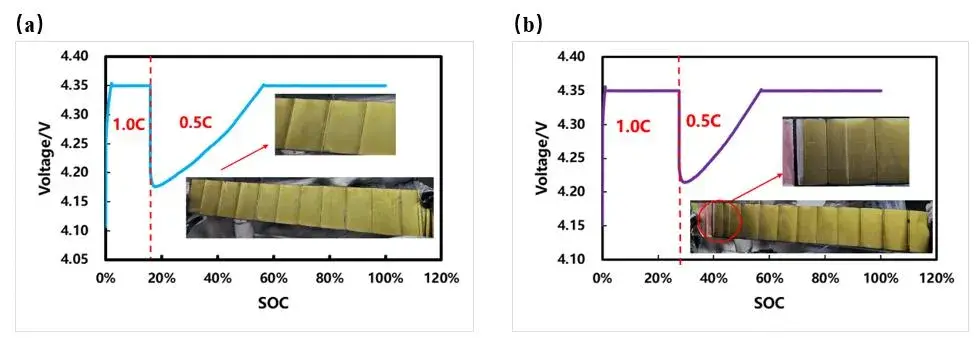
Figure 4. Step-rate charging curves and disassembly images for undeposited-lithium (a) and deposited-lithium (b) cells
To further verify the SOC at which lithium evolution begins, we conducted two sets of step charging experiments at different rates: before and after the inflection point of the thickness swelling curve appears, charging is switched to a smaller rate. A group of cells is charged at a constant current of 1C to about 15.7% SOC and then charged at 0.5C to full power (as shown in Figure 4(a)); the other set of cells is charged at 1C constant current to approximately 27.4% SOC and then charged at 0.5C to full power (Figure 4(b)). After dismantling the battery core, it was found that slight lithium plating occurred on the surface of the negative electrode after changing the rate to 27.4% SOC, and there was no lithium plating on the surface of the negative electrode after charging to 15.7% SOC. This shows that the lithium evolution SOC during 1C rate charging occurs between 15.7% and 27.4%. Compared with Figure 3(a), it is basically consistent with the SOC position corresponding to when the slope of the 1C swelling thickness curve begins to bifurcate.
The solid-phase diffusion coefficient of lithium ions in graphite particles is related to the charge state of the material. As the SOC changes, when the solid-phase diffusion coefficient is relatively low, the lithium plating phenomenon is more likely to occur. This non-destructive lithium plating detection method can quickly determine the lithium plating SOC window during battery charging, providing effective guidance for formulating fast charging strategies.
[1] Qixin Gao, Jingteng Zhao, Guoxing Li. Research progress on fast-charging lithium-ion batteries. Energy Storage Science and Technology, 2023, 12: 2166-2184.
[2] Guoxing Li. Regulating mass transport behavior for high-performance lithium metal batteries and fast-charging lithium-ion batteries. Advanced Energy Materials, 2021, 11:202002891.
[3] Chandrasekaran R. Quantification of bottlenecks to fast charging of lithium-ion-insertion cells for electric vehicles. Journal of Power Sources, 2014, 271: 622-632.
[4] Waldmann T, Hogg B I, Wohlfahrt-Mehrens M. Li plating as unwanted side reaction in commercial Li-ion cells-A review. Journal of Power Sources, 2018, 384: 107-124.
[5] Anna Tomaszewska, Zhengyu Chu, Xuning Feng, Simon O’Kane, Xinhua Liu, Jingyi Chen, Chenzhen Ji, Elizabeth Endler, Ruihe Li, Lishuo Liu, Yalun Li, Siqi Zheng, Sebastian Vetterlein, Ming Gao, Jiuyu Du, Michael Parkes, Minggao Ouyang, Monica Marinescu, Gregory Offer, Billy Wu. Lithium-Ion Battery Fast Charging: A Review. eTransportation. 2019, 1: 100011.
The limitations of lithium-ion battery fast charging speed fall into six categories: electrode/electrolyte material properties, environmental temperature and humidity, charging method (constant current, constant voltage, or pulse), lithium plating risk, manufacturing process consistency, and safety limits on current and voltage. Lithium plating and low-temperature internal resistance increase are typically the most restrictive factors at high charging rates.
Fast-charging voltage and achievable current change with temperature because low temperature increases electrolyte viscosity and internal resistance, slowing lithium-ion diffusion. Voltage behavior also changes with SOC because, as state of charge rises, the negative electrode potential moves closer to the lithium plating threshold (0V vs Li⁺/Li), narrowing the safe voltage margin before lithium metal begins depositing on the electrode surface.
At low temperature, the solid-phase diffusion coefficient of Li⁺ in graphite decreases and electrolyte viscosity increases, slowing ion transport into the anode. At high SOC during CC-CV charging, the negative electrode potential is already closer to 0V vs Li⁺/Li. When either condition slows Li⁺ insertion below the rate at which ions arrive at the electrode surface, lithium accumulates and plates out as metal rather than intercalating, which is why lithium plating is most commonly observed under combined low-temperature, high-SOC fast-charging conditions.
The IEST SWE In-Situ Cell Swelling Testing System measures cell thickness (swelling) continuously during charging at different rates. A “bifurcation” in the swelling-thickness curve relative to lower, lithium-plating-free rates indicates the onset of lithium plating. Step-rate charging experiments that switch to a lower rate before and after this inflection point, followed by disassembly verification, narrow down the precise SOC window — for example, between 15.7% and 27.4% SOC in a 1C-rate test case — without requiring disassembly of every sample.
Constant current charging maintains a fixed current and charges quickly but is unsuitable for extended use as terminal voltage rises. Constant voltage charging maintains a fixed voltage, is suitable for longer charging periods, but slows as current decreases and can increase material stress from greater delithiation/lithiation. Pulse charging alternates short charging bursts with pauses, which can reduce polarization and internal resistance buildup, improving charging speed and efficiency compared with continuous constant current charging alone.
Yes. Traditional detection requires disassembling a fully charged cell to visually inspect the negative electrode for gray-white lithium deposits, which is destructive and only approximate. Non-destructive in-situ methods — such as three-electrode potential monitoring or in-situ cell swelling measurement with the IEST SWE system — can determine the lithium plating voltage and SOC window during active charging without destroying the sample.
Pulse charging alternates active charging periods with short pauses, allowing the concentration gradient of lithium ions near the electrode surface to relax during the pause. This reduces polarization and helps prevent the negative electrode potential from dropping to the lithium plating threshold as quickly as it would under continuous constant current charging at the same average rate, though the degree of benefit depends on pulse frequency, duty cycle, and cell design.
