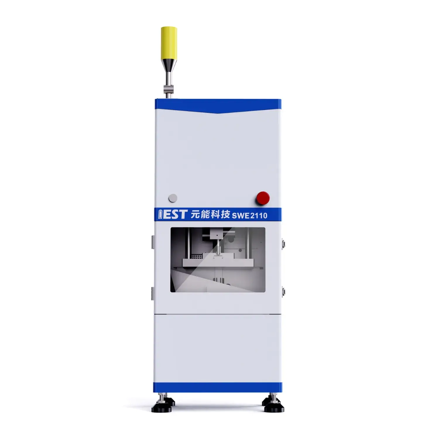
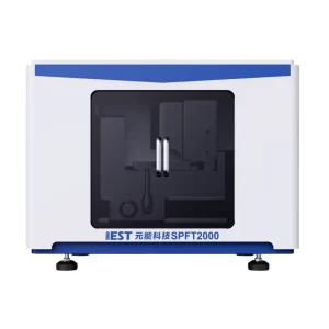
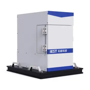
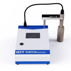
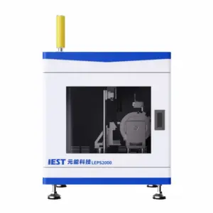
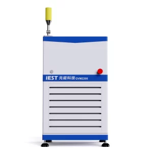
Introduction: The SWE Series is a premier in-situ characterization platform engineered for the high-precision evaluation of electrochemical-mechanical coupling dynamics in battery cells. Driven by an advanced servo-motor control matrix and high-sensitivity multi-sensor arrays, it delivers simultaneous, real-time quantification of both volumetric swelling thickness variance and expansion force evolution during live cycling. Featuring innovative non-destructive lithium plating detection and wide-range temperature regulation, suitable for battery R&D and material evaluation.
Features:
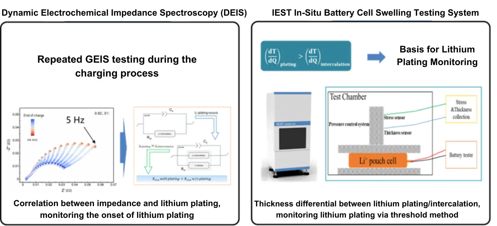
In-situ non-destructive lithium plating detection: Leverages an innovative, non-destructive electrochemical-mechanical diagnostic method to capture the early onset and growth kinetics of metallic lithium plating in situ, establishing safe fast-charging boundaries.
Ten-Ton Multi-Scale Mechanical Constraint: Features an wide force envelope scaling(5kg/100kg/300kg/1000kg/5000kg/10000kg), seamlessly accommodating everything from delicate pouch cells to heavy-duty prismatic and next-gen short-blade cells.
Multiple Test Modes: Supports three precise mechanical boundary modes—including constant pressure simulation, constant gap (constant volume) tracking, and compression profiling—to accurately replicate real-world pack assembly environments.
Thermal & Multi-Channel Synchronization: Interlocks a wide-range thermal matrix (-20°C to 80°C) with scalable multi-channel execution (from single to four-channel parallel tracking) for high-throughput, accelerated cell degradation and aging studies.
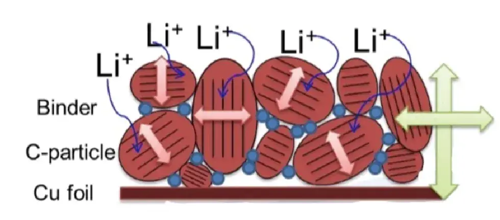
During the charging and discharging process of lithium-ion batteries, the insertion and extraction of lithium ions in the positive and negative electrode materials cause reversible expansion and contraction of the cell. At the same time, side reactions such as particle cracking, SEI film rupture, and cell deformation occur, leading to irreversible deformation. Thus the swelling behavior of the battery cell becomes an impotant indicator for evaluating the reliability of the Lithium batteies.
On the other hand, the lithium plating also can cause the expansion of LIBs. Thus, how to identify the lithium plating window under different charging rate and temperature by the expansion behavior of LIBs is very helpful for the developments of the fast charging technology, sectional charging technology and other charging strategies.
2. Traditional Methods for Swelling Evaluation
Disassemble different—condition cells and measure the thickness of the cell and electrodes by micrometer;
Li plating window judgment: Through the disassembly of full charged cell to judge the lithium precipitation on electrode surface by visual inspection;
Destructive Test: It is a cell consuming destructive test, and there is a higher safety risk and higher operation cost because the dry environment and professional people are required;
Non in-site Test: Only the thickness data on several specific states can be acquired, the swelling behavior of cells cannot be described systemically; Big Deviation for lithium plating window assessment: Not every lithium plating SOC and potential in different rate can be quantified.
3. IEST Creative Swelling Solutions
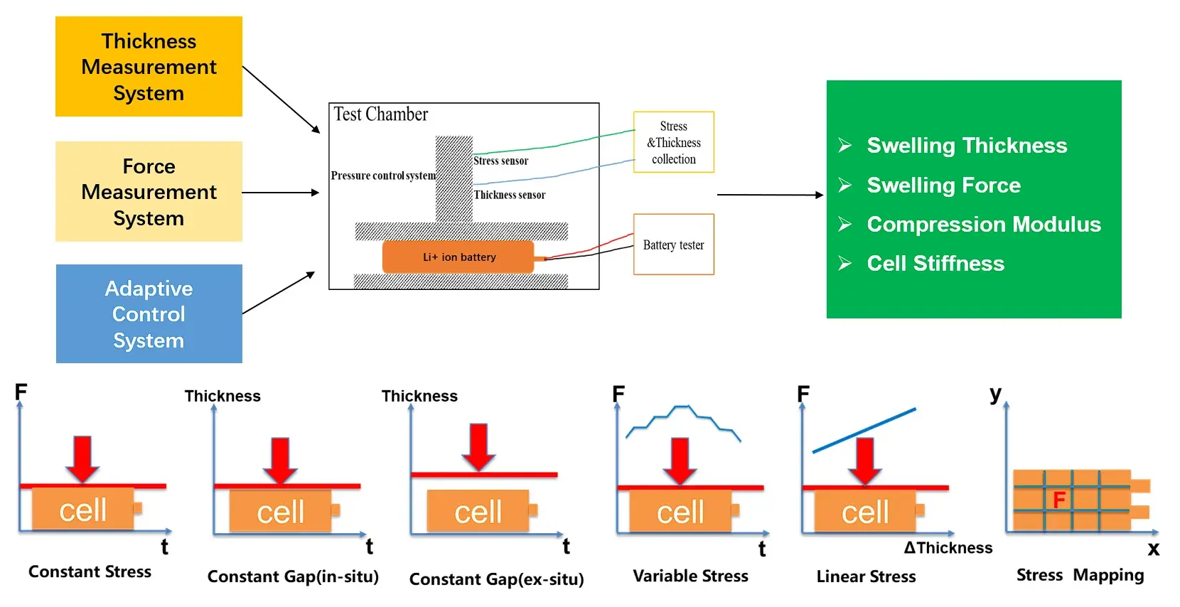
In-situ swelling analysis system: Combined with the highly stable automatic platform and the high-precision thickness and mechanical sensors, it can achieve long-term stability and accurately detect the expansion thickness and the expansion force under different conditions.
Multi-function test modes: the constant pressure and constant gap test modes can be realized for the cell, and the performance of the cell under different stress conditions can be evaluated.
High precision control: The traditional fixture will generate ~70um deformation under the constant gap testing mode, which leads to the inaccurate swelling force test. However. the in-situ SWE series analysis system of IEST can control the change of the gap within ~1um by active modulation, and record the accurate swelling force during the constant gap testing mode.
4. SWE Series Instrument Schematic
Six Test Modes: Characterize the expansion behavior of the battery cell under different boundary conditions.
The In-situ Swelling Analysis System Integrates: high-precision servo motor + adaptive lower-level control system + high-precision pressure sensor and thickness sensor
5. Applicable Samples
Customization available according to cell size and maximum swelling force.
6. Applications
Material Evaluation
Operational Condition Evaluation
Lithium Plating Evaluation
Cell Structure Evaluation
Cell Stiffness Evaluation
Swelling Force Distribution
Applications
1. Application Cases: Material Evaluations
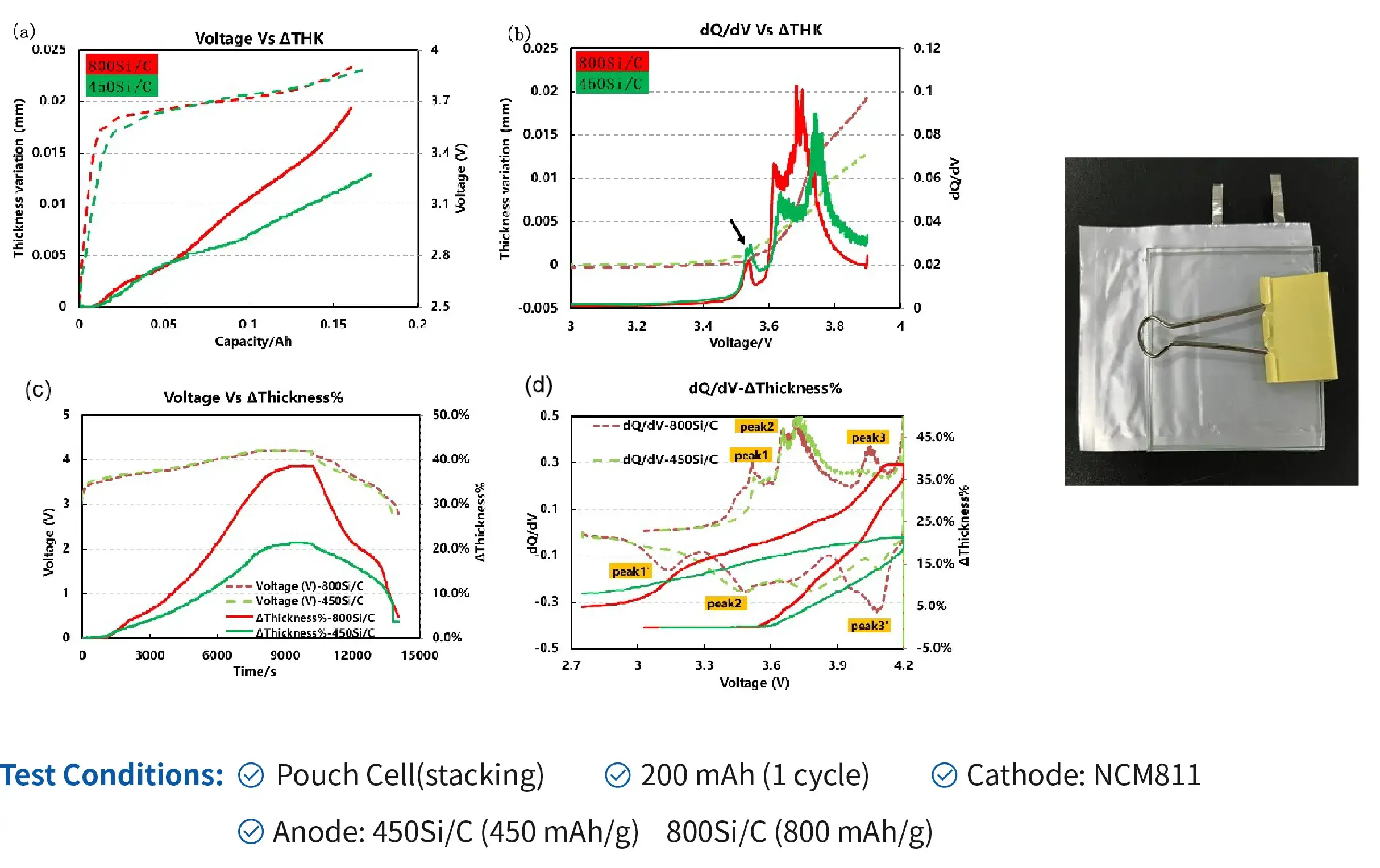
1.1 Formation and Charge-discharge Swelling of Cells With Different Si/C Contents
Higher silicon content in the anode leads to greater expansion caused by lithium-ion intercalation forming the LixSi alloy, and will also affect the lithium intercalation phase transition potential of graphite.
R&D personnel should rationally regulate the silicon-to-carbon ratio and modify the structure of silicon-based materials to mitigate structural expansion.
1.2 NCM-Si/C Cell – Compare the Swelling Differences of Various Modified Si/C Materials
Anode: Three types of Si/C electrodes (B, C, D) with similar capacities (approximately 5.9 mAh) but different modification methods. (Material B is a low-expansion silicon-carbon material specially modified by a Ningbo battery materials company.)
When paired with identical cathode materials, comparative swelling analysis revealed that the specially modified Si/C material (B) exhibited minimal thickness expansion.
The swelling thickness trends aligned statistically with cross-sectional SEM measurements
1.3 Cycle Swelling of Cells With Different Binders
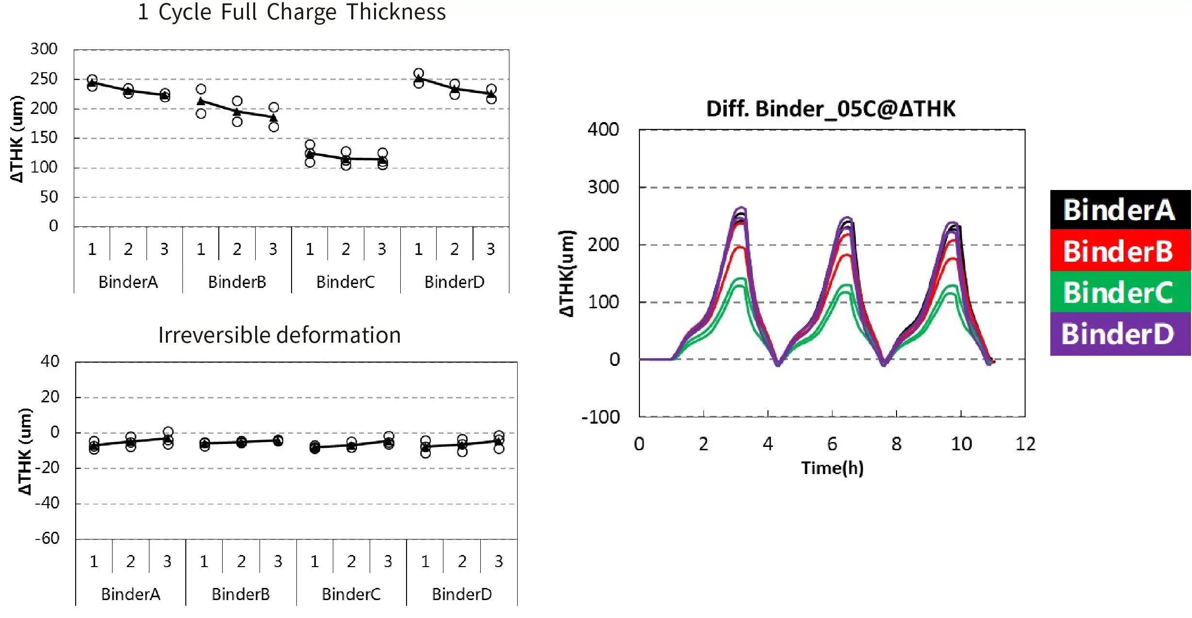
Comparison of battery cells swelling with four different binder materials: The irreversible swelling levels are comparable, with the main difference observed in the single-cycle full-charge swelling thickness. Binder C demonstrates the best swelling suppression performance.
This approach serves can be used for evaluation and screening of different binder materials.
1.4 Lithium Metal Anodes with Distinct Modification Approaches
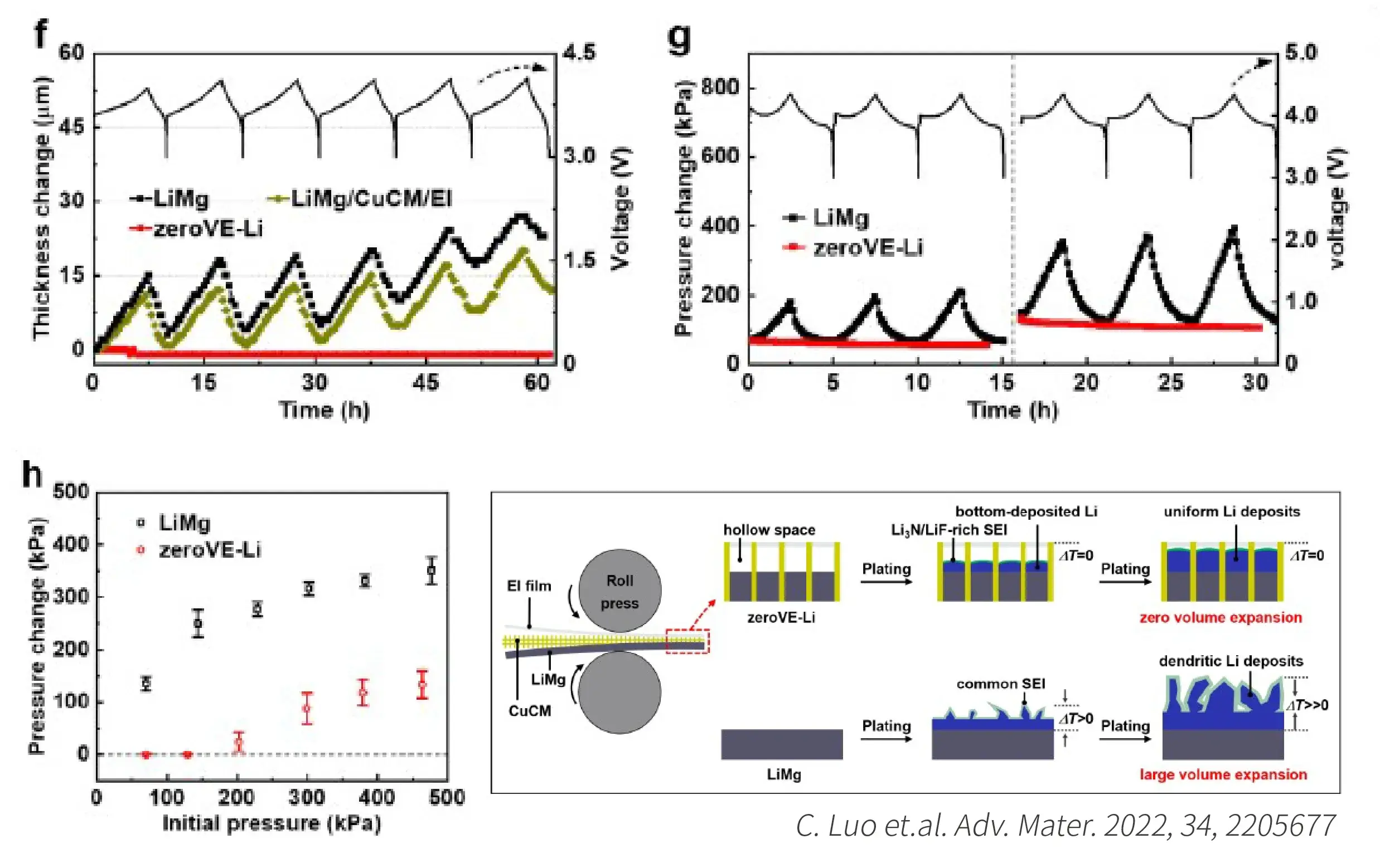
Modified lithium metal anodes significantly suppress volume expansion during cycling.
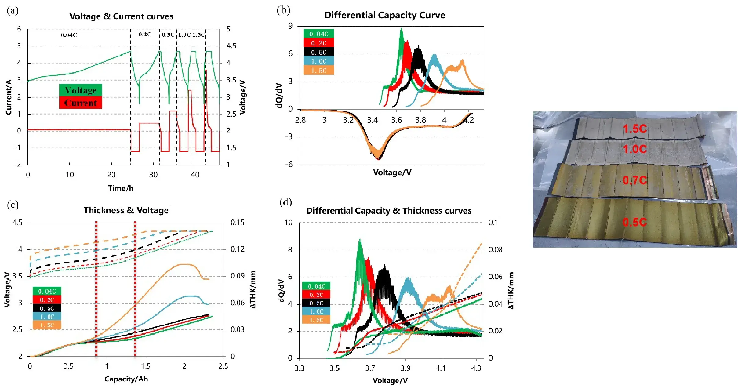
Testing Method: In-situ testing of the cell’s thickness curve at different charging C-rates.
Determination Method: The C-rate at which the thickness curve diverges from the lithium plating-free low C-rate thickness curve is identified as the lithium plating window.
2.2 Lithium Plating Under Different Tempreture
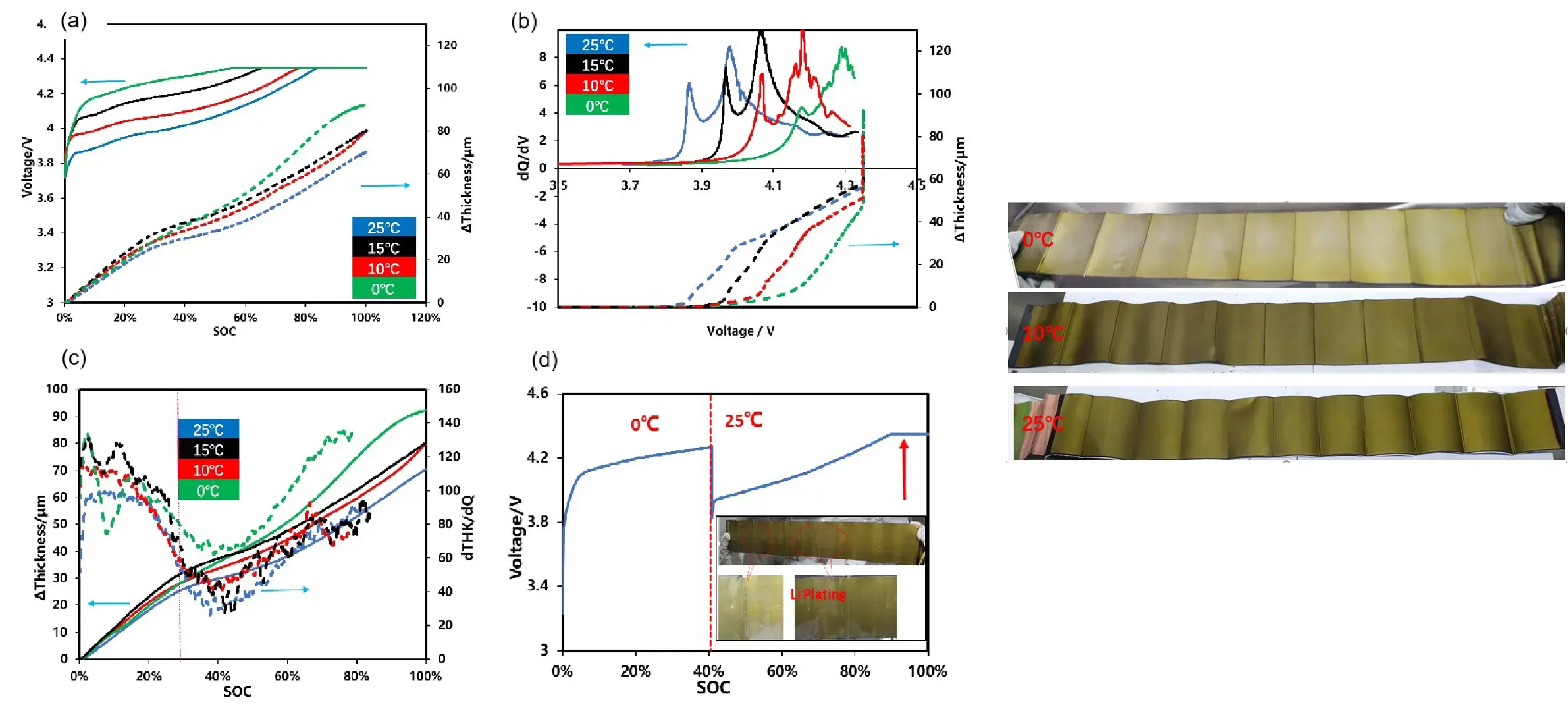
Testing Method: In-situ testing of the cell’s thickness curve at different temperatures.
Determination Method: The temperature at which the thickness curve diverges from the lithium plating-free higher temperature thickness curve is identified as the lithium plating window.
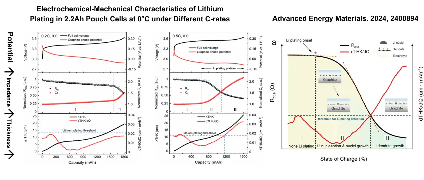
2.3 Analysis of the Three-Stage Lithium Plating Process on Graphite Surface in Pouch Cells
By correlating changes in the anode charge transfer resistance (Rct,a) using the impedance method, the onset of lithium plating nucleation can be monitored.
The three-stage decline pattern of Rct,a indicates distinct phases of lithium plating. The impedance method and thickness method show consistent results in monitoring lithium plating.
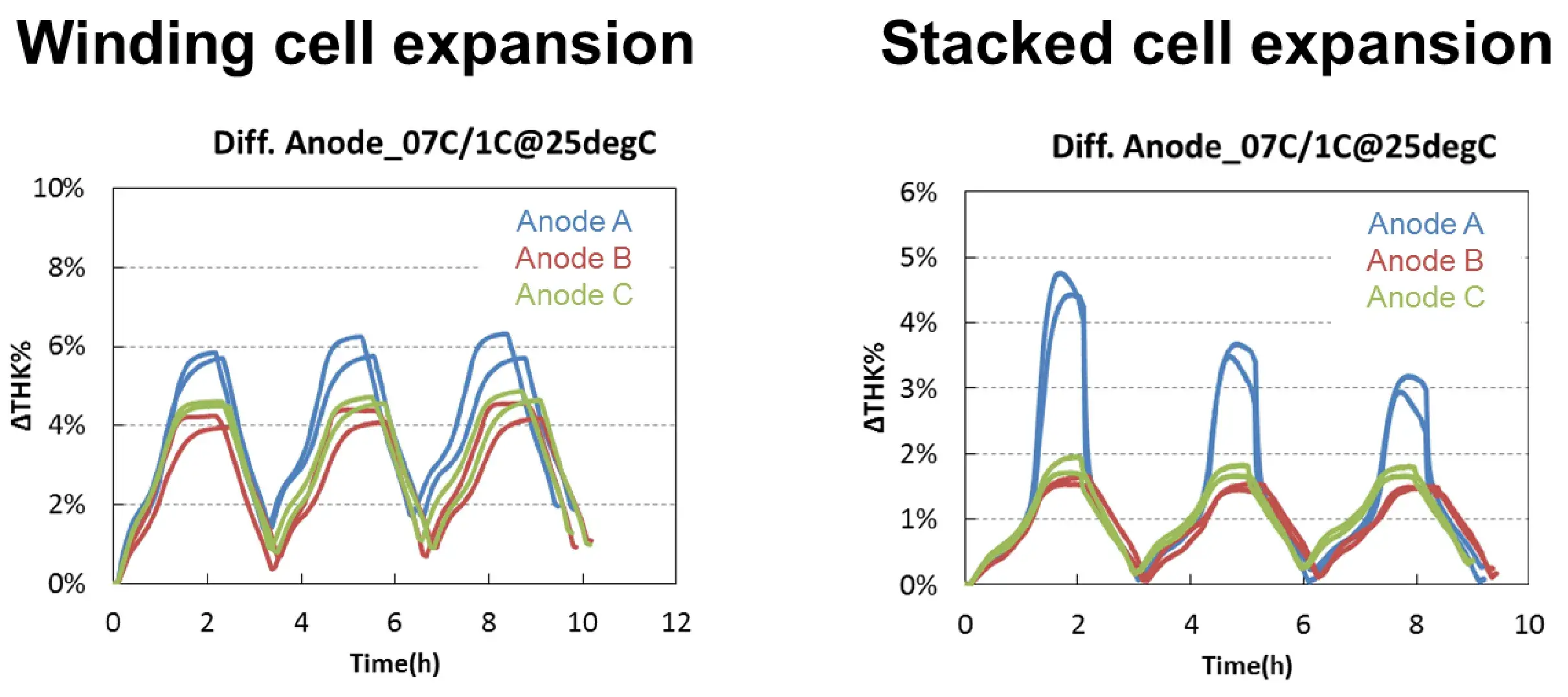
3.1 Multi-Layer Wound vs. Single-Layer Stacked Structure Comparison
Two models are used to evaluate the swelling of different anode cells, and the comparison law is basically the same as A> C> B.
Because the two sides of the winding are bound, the crimping stress caused by the lateral swelling accumulates in the middle, so that the thickness increases with the cycle, and the four sides of the lamination are not bound, so the crimp stress of the group A pole piece with larger lateral swelling is released during the cycle, and the thickness decreases with the cycle. (Single-sided anode).
In-situ Cell Swelling Testing System can be used to deeply analyze the influence of process on stress and strain.
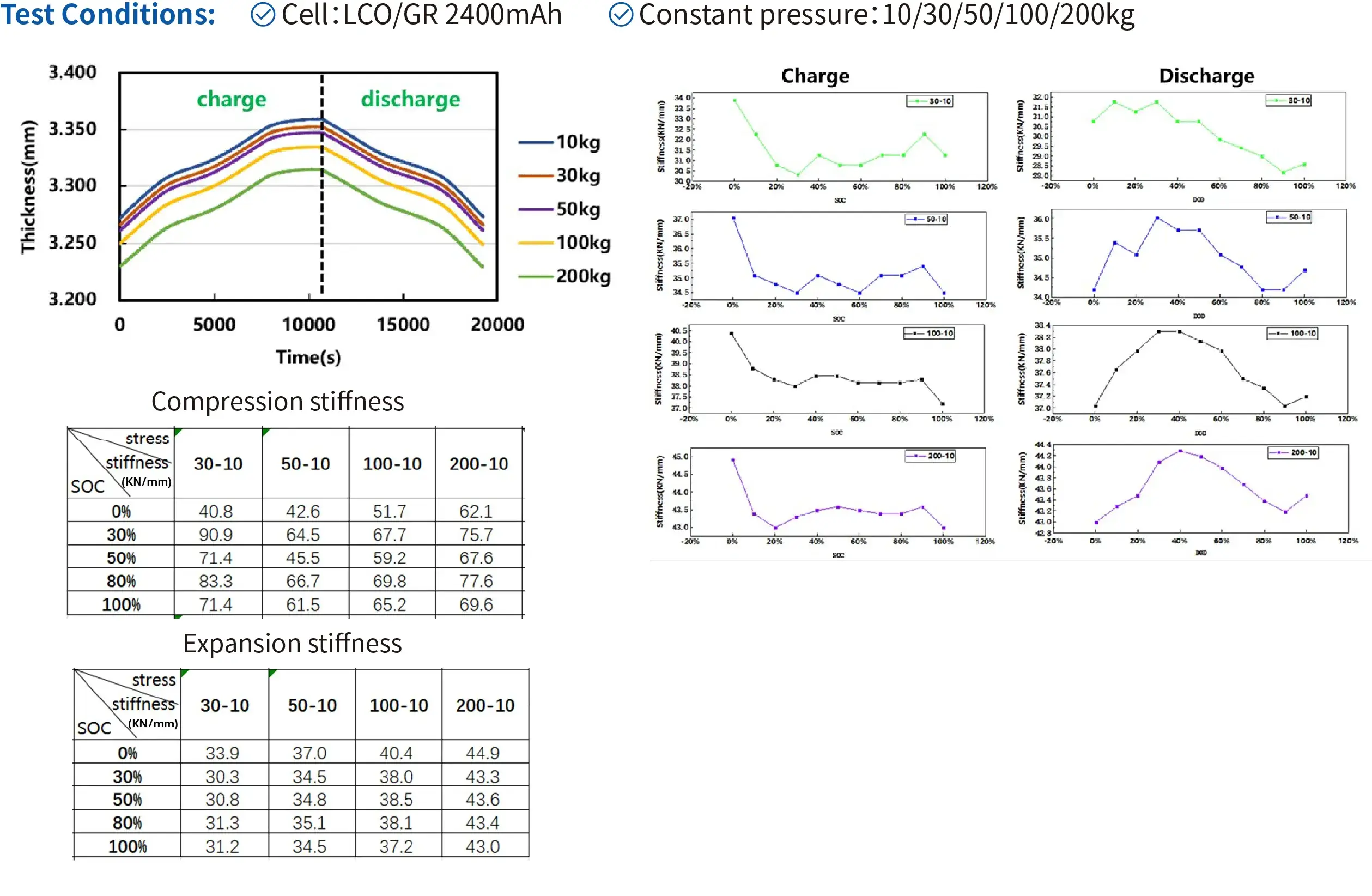
4. Swelling stiffness vs. Compression Stiffness Under Constant Pressure
The swelling stiffness changes regularly with charging and discharging.
The difference between swelling stiffness and compression stiffness is obvious.
5.1 Swelling of Pismatic Cells Under Different Stress
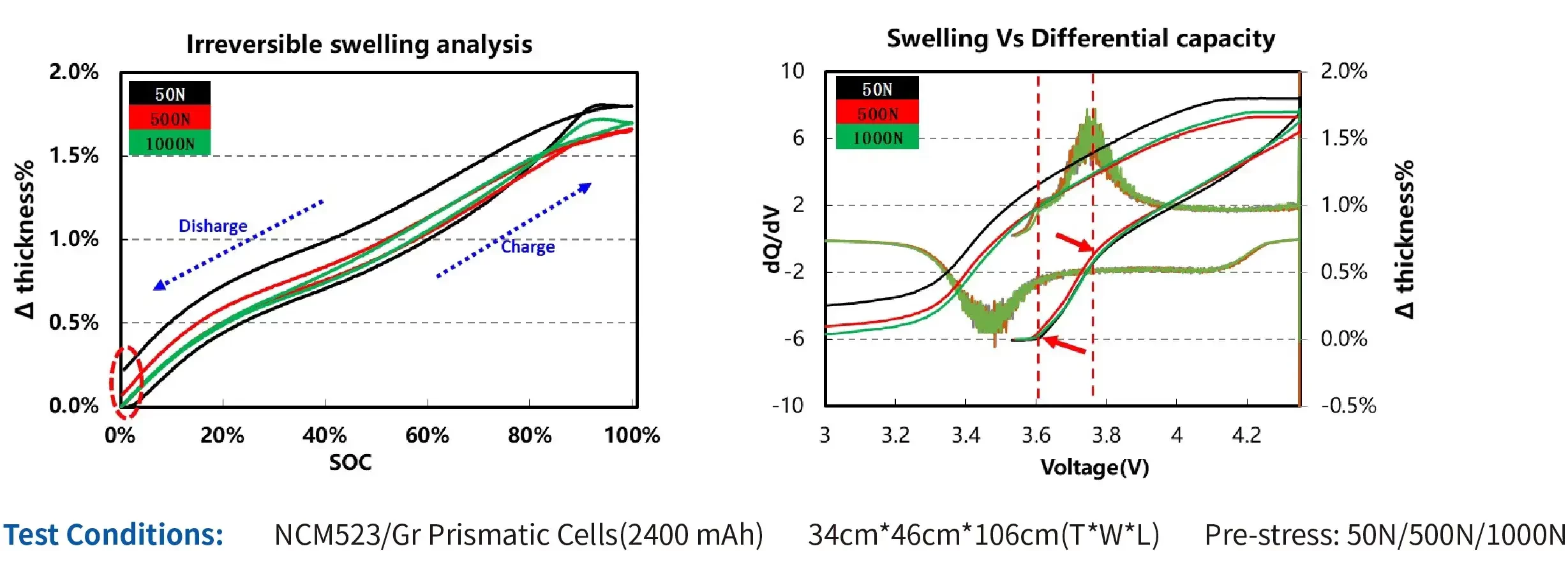
The proportion of irreversible swelling of the cells can be reduced by increasing the pre-stress.
During the charge process, the 2 inflection points of the swelling curve correspond to the 2 peaks of the diferential capacity curve, indicating that the swelling of the cell is related to the phase transition of lithium intercalation & deintercalation.
5.2 Swelling of Prismatic Cells Under Different Temperature
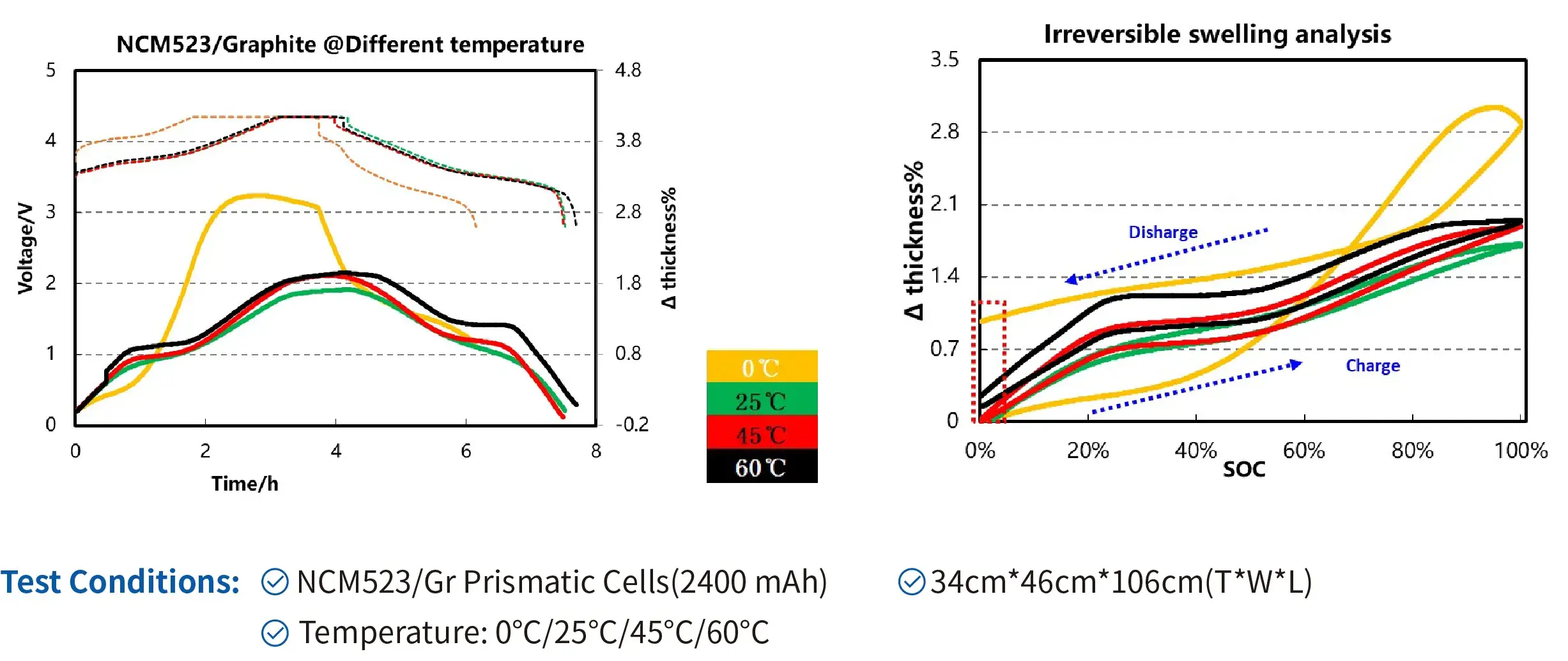
The irreversible swelling of the cells increases in both cases when the temperature increases from 25℃ to 60℃, as well as decreases from 25℃ to 0℃. However, the causes of such swelling under high-temperature and low-temperature conditions may differ.
5.3 Swelling of Prismatic Cells Under Different Charge Rate
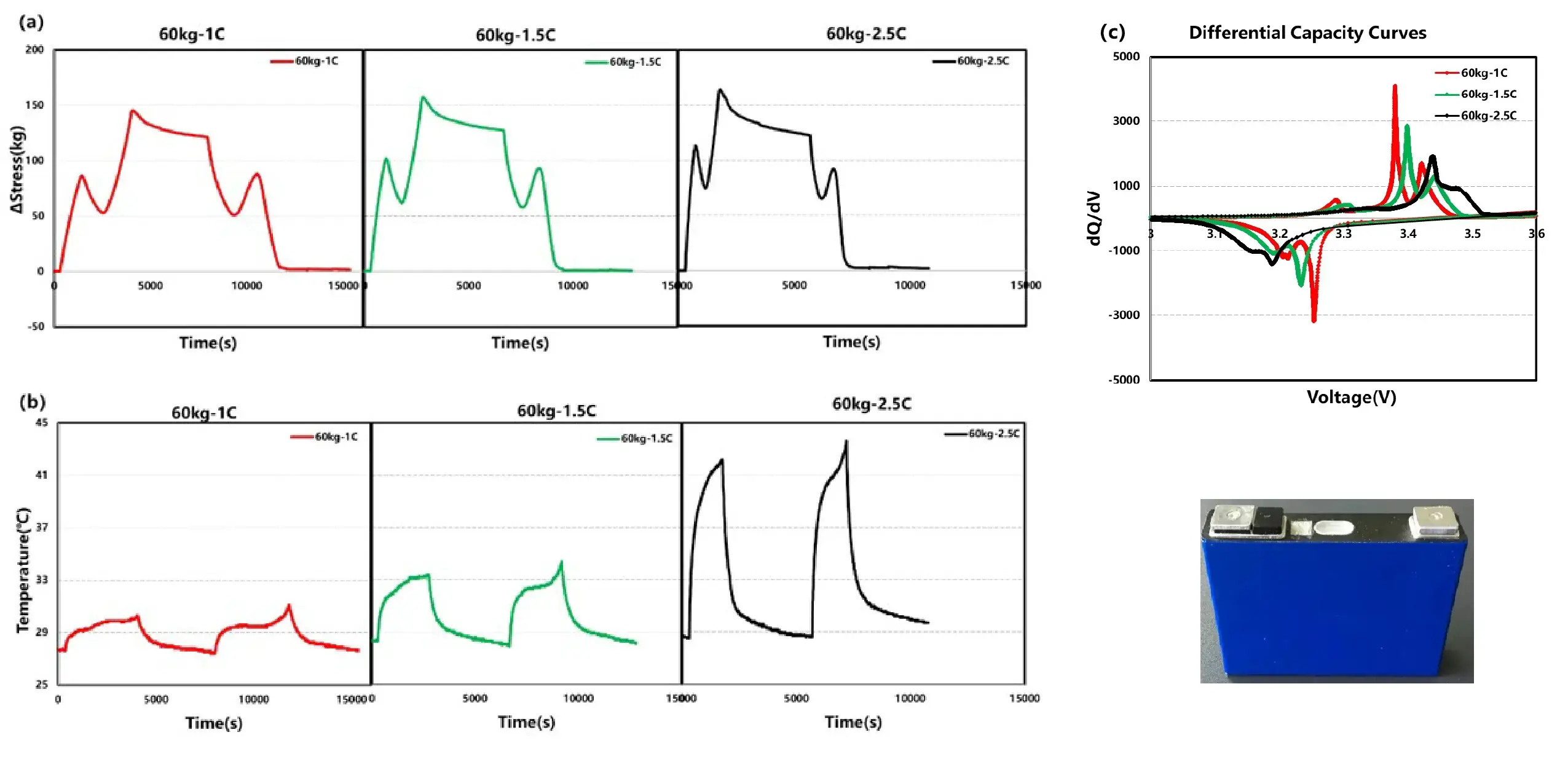
LEP/Graphite 40Ah Prismatic Cell
As the charge rate increases, the cell’s temperature rise progressively intensifies. This trend predicts that exceeding certain C-rate thresholds may trigger excessive temperature elevation and potential thermal runaway.
5.4 Swelling of Prismatic Cells Under Different Preload Force
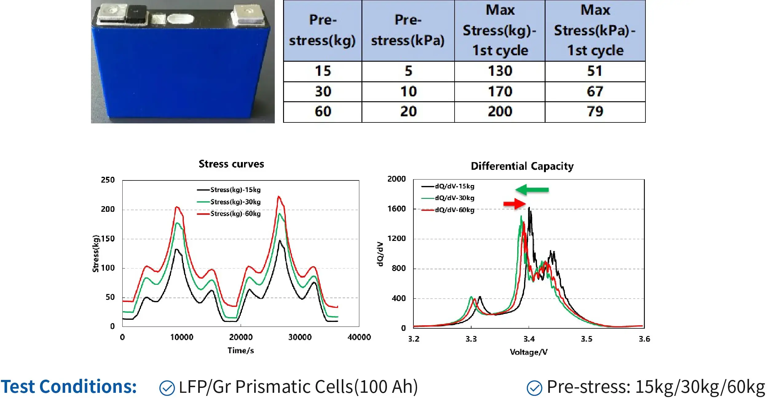
Preload Force vs. Swelling Force & Module Design: As the preload force increases, the initial gap of the cell gradually decreases, and the swelling force variation during charge-discharge cycling becomes increasingly pronounced. This further establishes the correlation between the initial preload force and the maximum swelling force, providing critical guidance for battery module structural design.
Preload Force vs. Polarization & Rate Performance: With increasing preload force, the cell’s charging polarization first decreases and then increases. This indicates that for this prismatic hard-cased cell, an optimal preload force of approximately 30 kg is beneficial for enhancing rate performance.
5.5 Thickness and Stress Changes During Charge and Discharge
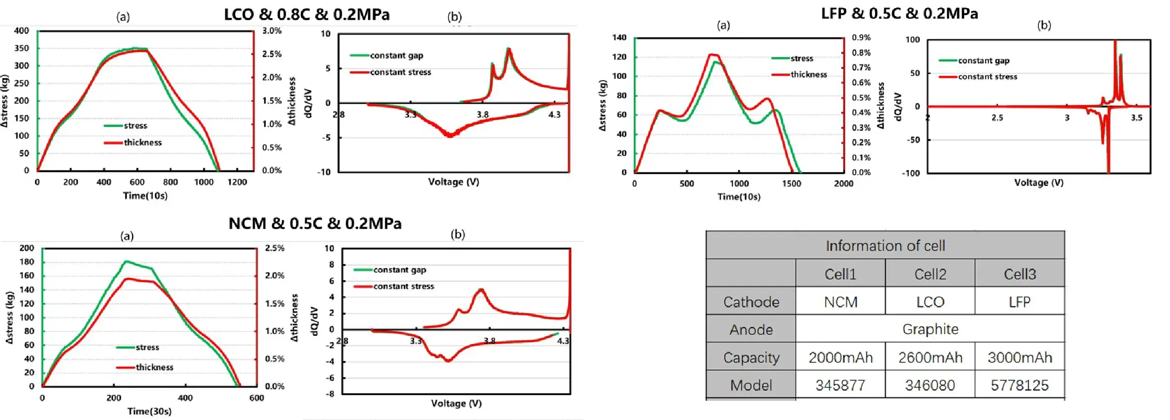
Swelling Behavior Across Chemistries: LFP-based cells exhibit a characteristic “camel hump” swelling phenomenon during charge and discharge cycling, which is absent in LCO and NCM systems. Furthermore, NCM cells display a slight reduction in swelling during the constant-voltage (CV) charging stage.
In-Situ R&D & Mechanistic Insights: Comparative analysis of these distinct swelling behaviors not only provides battery R&D researchers with an effective in-situ method to characterize cell swelling performance, but also offers vital mechanistic data references when investigating the expansion dynamics of specific chemical systems.
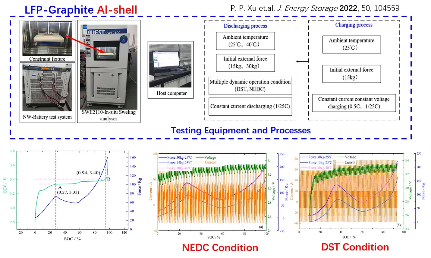
5.6 Prismatic Cells: SOC Estimation Based on Swelling Force
An SOC estimation method for LFP cells utilizing swelling force, powered by LSSVM and AUKF algorithms, achieves an estimation error of less than 1% and is applicable across diverse operating conditions, including varying temperatures, dynamic current profiles, and preload forces.
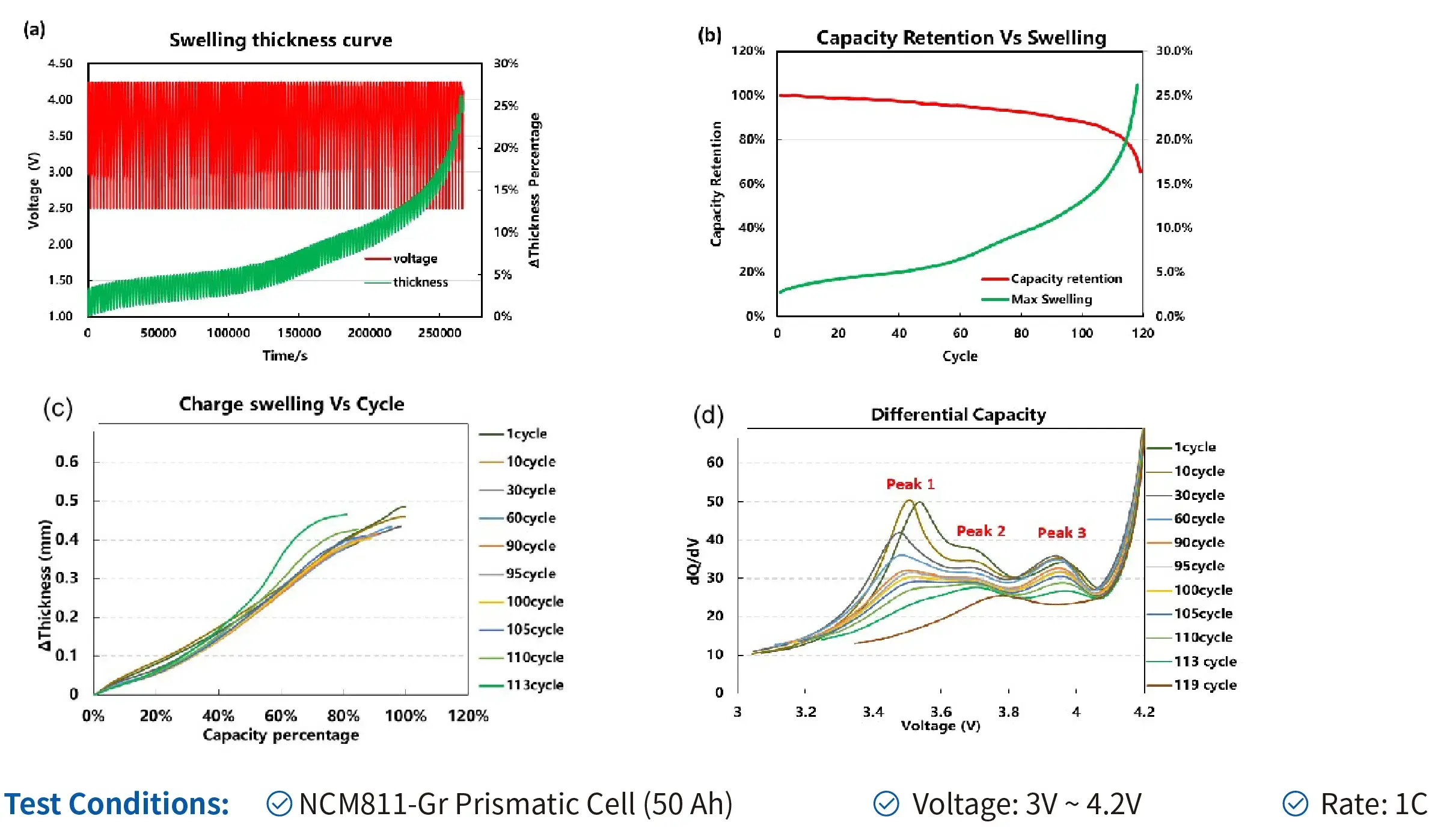
5.7 Cyclic Swelling Analysis
Investigating the correlation between capacity fade and thickness expansion in NCM cells during long-term cycling. Through comprehensive analysis of cell swelling thickness and electrochemical data, we infer that the cycling degradation mechanisms include electrode mechanical degradation, lithium plating, and parasitic side reactions.
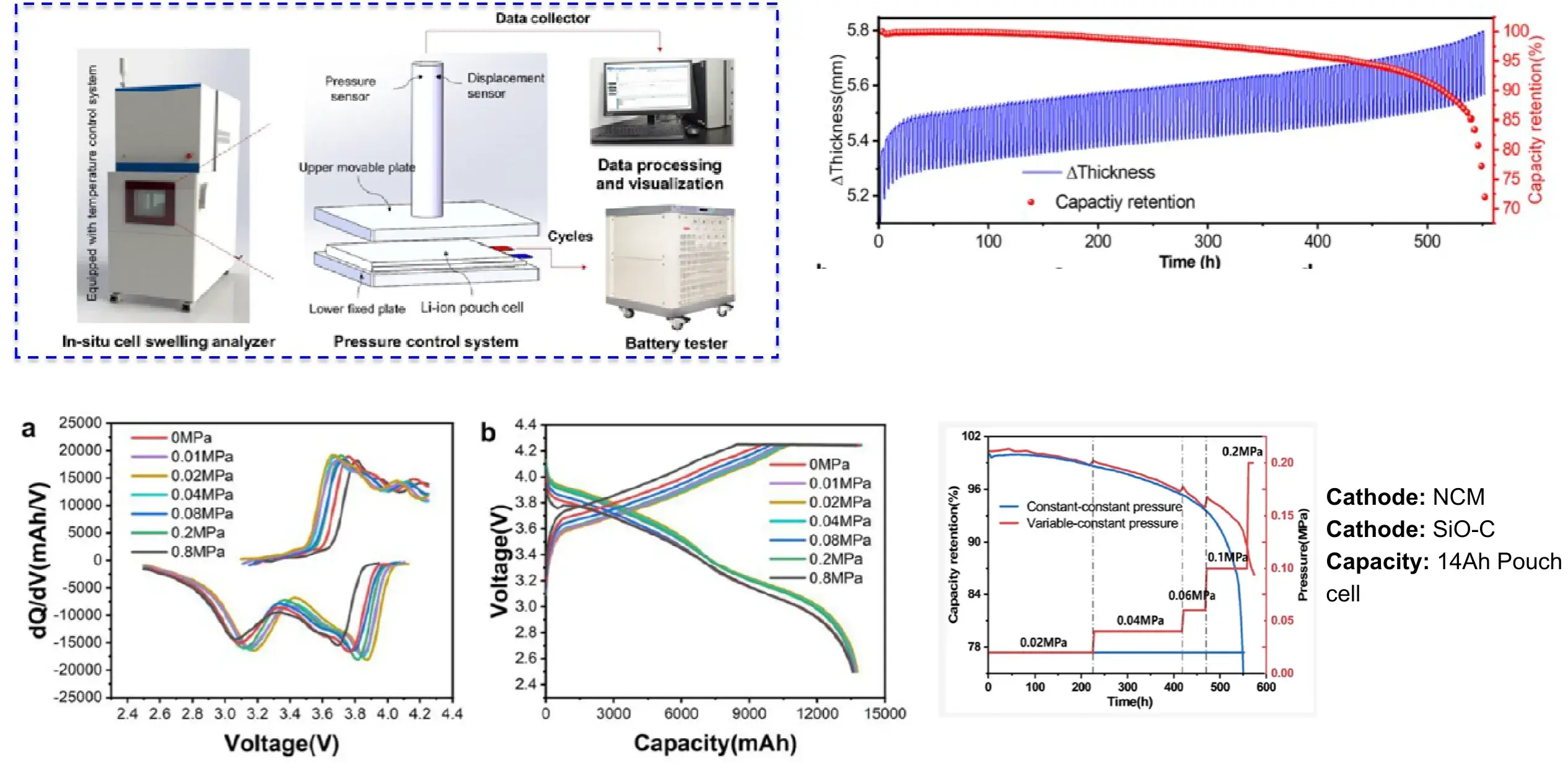
5.8 Constant Stress Test Analysis
Optimal external pressure mitigates cell polarization during cycling. Implementing stepwise external pressure throughout battery operation significantly extends cycle life.
These findings establish an effective strategy for capacity enhancement in lithium-ion batteries featuring silicon-dominant anodes, providing critical guidance for pack engineering design.
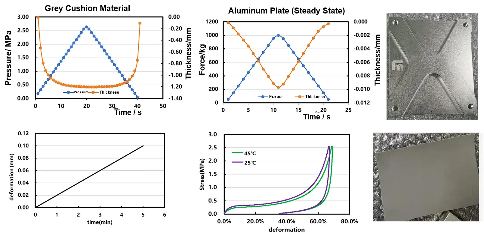
6. Fatigue Strength of Solid-State Fixtures & Cushion Foam
Analyze material elastic and plastic deformation to select suitable materials.
7. Swelling stiffness vs. Compression Stiffness Under Constant Pressure
The swelling stiffness changes regularly with charging and discharging.
The difference between swelling stiffness and compression stiffness is obvious.