-
iestinstrument
A Comprehensive Analysis of Compression and Conductivity in Silicon-Carbon and Silicon Monoxide Anode Materials
1. Abstract
Silicon-based anodes promise substantially higher specific capacity than graphite, but practical deployment requires careful control of volumetric expansion, conductivity and packing. This study compares three Si–C mixtures (3%, 6%, 10% Si) and four carbon-coated silicon monoxide (SiO) variants prepared at increasing sintering temperatures, using SEM, powder resistivity, compaction density and uniaxial compression testing (PRCD3100). Our results demonstrate that increasing silicon fraction degrades bulk electrical conductivity and reduces compacted density, while higher sintering temperatures tend to improve SiO conductivity and compressive strength. These findings point to clear electrode-design levers—conductive-additive strategy, tailored compacted density and carbon coating quality—that help reconcile the competing demands of capacity, cycle life and mechanical tolerance in silicon-based anode formulations.
2. Introduction: The Promise and Challenge of Silicon-Based Anodes
Lithium-ion batteries (LIBs), valued for their high energy density and long cycle life, are dominant in portable electronics and electric vehicles. However, the capacity of traditional graphite anodes is approaching its limit for meeting the demand for longer driving ranges. Silicon-based anode materials, with their exceptionally high theoretical specific capacity (4200 mAh/g for pure Si), low discharge plateau, and natural abundance, are the most promising candidates for next-generation LIBs.
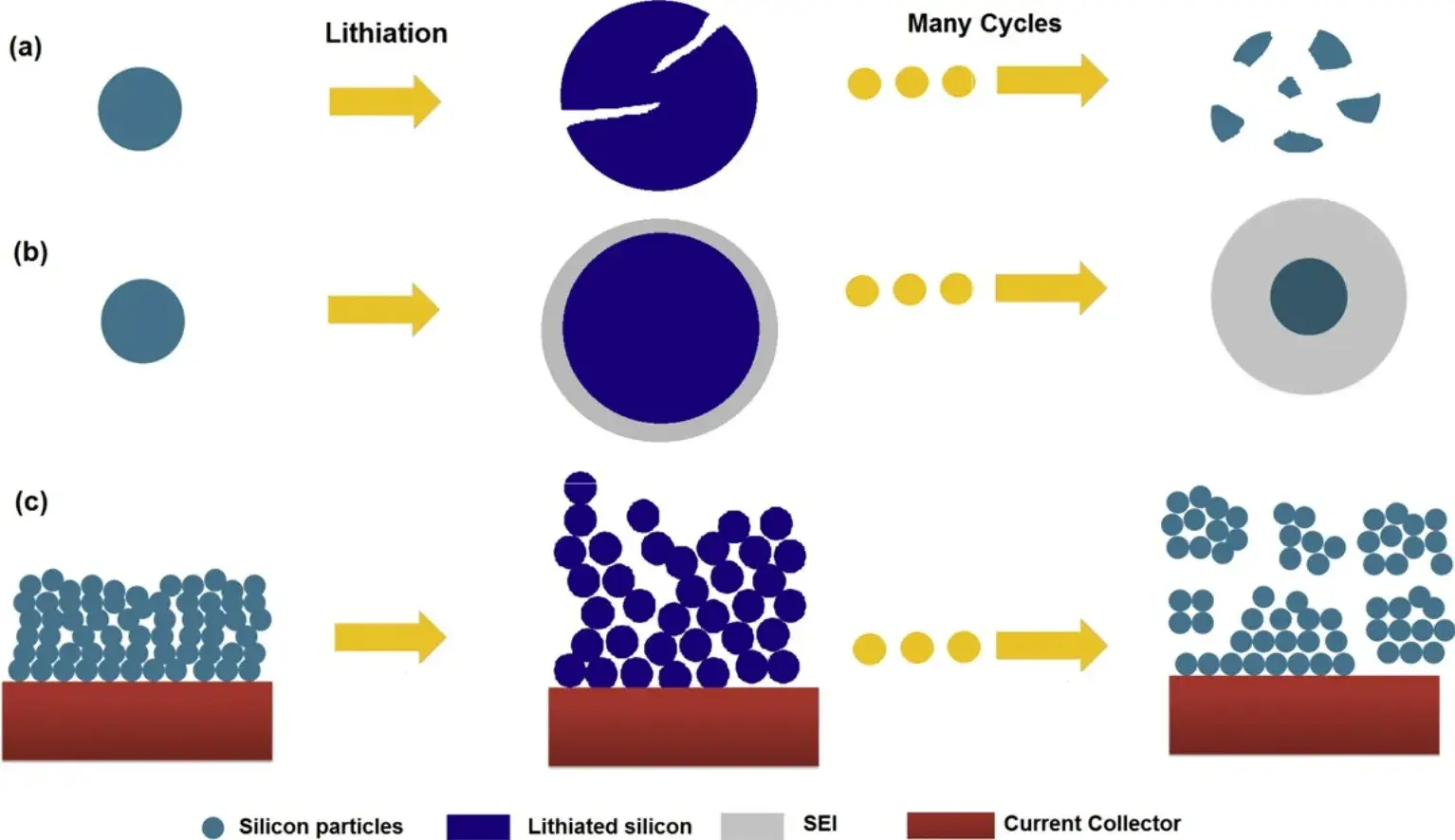
Yet, the commercial adoption of silicon faces significant hurdles. The primary challenge is the massive volume expansion (up to ~300%) during lithiation and delithiation. This expansion generates severe mechanical stress, leading to particle pulverization, loss of electrical contact with the current collector, and continuous growth of the solid-electrolyte interphase (SEI). These factors collectively cause rapid electrochemical performance degradation, as shown in Figure 1, which is a schematic representation of the failure mechanism of silicon.Additionally, silicon suffers from intrinsically low electrical conductivity and slow lithium-ion diffusion kinetics.
To address these issues, research focuses on nano-structuring and compositing. Practical applications primarily involve doping silicon with carbon or designing modified silicon structures (e.g., silicon monoxide, SiO) to enhance conductivity and accommodate volume change. This study provides a systematic analysis of the compression behavior and electrical conductivity of such composite materials.

Figure 1. Failure mechanism of Si electrode: (a) material crushing; (b) shape and volume change of the whole Si electrode; (c)SEI continues to grow ¹.
3. Testing Methodology
Our evaluation combined multiple characterization techniques:
-
SEM Morphology: Imaging of Silicon Monoxide(SiO) and Si/C materials.
-
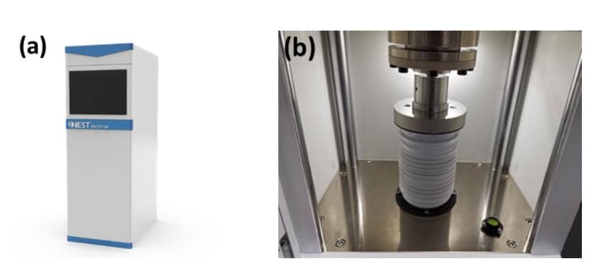
Integrated Powder Analysis: Using the IEST PRCD3100 system, we performed simultaneous measurements of powder resistivity, compaction density (tapping density), and compression performance. The testing protocol applied pressure from 10 to 200 MPa in 10 MPa steps, with a 10-second hold at each step.
Figure 2. (a) Appearance of PRCD3100; (b) Structure of PRCD3100
4. Test results
4.1 Analysis of Silicon-Carbon (Si/C) Composite Materials
We selected three Si/C composites with silicon contents of 3% (SiC-1), 6% (SiC-2), and 10% (SiC-3), and test the differences in electronic conductivity, compaction density and compression properties.
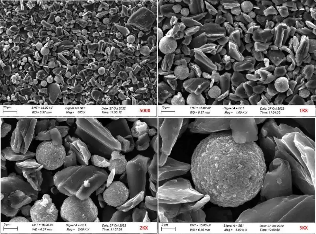
Combined with the scanning electron microscope, the three materials were compared with each other in terms of the differences in morphology, which could not be seen under the electron microscope due to the low silica content and the differences in sample preparation. As shown in Figure 3, the SEM morphology at different magnifications with 6% Si content, where the Si material morphology is mostly spherical, with a particle size of 5-10 μm.
The swelling and cracking of silicon particles is often related to the size of the particles. Generally speaking, the cracking of larger-sized μm-sized silicon particles is more severe, while the nano-sized particles with a size smaller than a certain critical value will have fewer cracks. The best way to utilize μm-sized Si particles is to compound them with graphite.

Figure 3. SEM morphology of the same SiC hybrid material at different magnifications
In order to further evaluate the difference of mixed materials with different silicon contents, this part uses the PRCD series powder resistivity &compaction density dual-function equipment to evaluate the conductivity, compaction density and compression performance. Figure 4 and Table 1 show the stress-strain curves and deformation comparisons of the three materials respectively. From the perspective of deformation ratio, the elastic and plastic deformations of the three materials are not much different. This shows that the addition of a small amount of silicon spheres has little effect on the overall deformation of the carbon material.
Table 1.Summary of Deformation Data of Three Silicon-carbon Composite Materials
![]()
![]()
Figure 4. Stress-strain curves of three silicon-carbon composite materials
Figure 5 shows the measurement results of the resistivity and compaction density of the three materials as a function of pressure. It can be seen from Figure (A) that as the proportion of silicon increases, the conductivity of the mixed material gradually deteriorates, this is mainly due to the poor conductivity of the silicon material, which leads to poor overall performance of the hybrid material as its proportion increases.
As for the measurement results of the compacted density of the three materials (B), it can be seen that as the proportion of silicon material increases, the compacted density tends to decrease significantly, this is mainly because the compaction density of silicon materials is relatively small compared to carbon materials, and in mixed materials, there will be obvious changes with the proportion difference between materials.
Therefore, the design and preparation of the electrode of the silicon-carbon composite anode needs to optimize the electrode parameters such as the conductive agent formulation and compaction density of the electrode. Studies have shown that compared with graphite anodes, appropriately reducing the compaction density and increasing porosity of silicon-carbon anodes is conducive to buffering the volume swelling of silicon particles and inhibiting crack generation. On the one hand, the conductive agent uses a zero-dimensional conductive agent to coat the active particles to form a tight short-range electronic conduction network, and uses a one-dimensional conductive agent such as CNT to form a long-range electronic conduction network from the current collector to the entire electrode thickness direction.
![]()
Figure 5. (A)Variation of resistivity with pressure for three silicon-carbon composite materials
![]()
Figure 6. (B)Variation of compacion density with compression for three silicon-carbon composite
4.2 Analysis of Carbon-Coated Silicon Monoxide (SiO) Materials
Compared with pure silicon, the silicon monoxide (SiO)-based composites material reacts during the first lithium embedding process to generate Li₂O, Li₄SiO₄, and Si in situ, of which Li₂O and Li₄SiO₄ are electrochemically inert components that do not take part in subsequent electrochemical reactions, and are evenly dispersed with each other with the generated monomaterial Si. chemical reaction, and the generated monolithic Si is uniformly dispersed with each other, which largely buffers the volume expansion of monolithic Si in the charge/discharge process and improves the cycling stability of the overall electrode material. However, SiO2-based materials still have the expansion effect in the process of de-embedded lithium, which leads to capacity degradation and poor electrical conductivity, and their applications are mainly modified by means of carbon coating, nanosizing, porous structure design, and composite with highly conductive phases, etc. The surface-coated 0.5 mm Si oxide-based materials were selected in this part.
In this part, four silicon monoxide (SiO)-based materials SiO-1, SiO-2, SiO-3 and SiO-4 (sintering temperature: SiO-1 < SiO-2 < SiO-3 < SiO-4) with 0.1% carbon coating on the surface and different sintering temperatures were analyzed from the angles of SEM morphology, electrical conductivity, compacted density, and compression properties, respectively. As Figure 7 shows the comparison of the differences in the morphology test of the four materials, there is no obvious difference between the four materials from the morphology results. Compared with the monolithic silica material, the silica oxide-based material presents an irregular surface loose morphology.
![]()
Figure 7. SEM morphology of four silicon monoxide (SiO)-based materials
Similarly, for silicon monoxide (SiO)-based materials, comparative tests and evaluations were carried out from the aspect of compressive properties. Figure 7 and Table 2 show the stress-strain curves and deformation comparisons of the four materials. From the perspective of deformation ratio, for the four materials with different sintering temperatures, the overall compressibility of SiO-2 and SiO-3 is not much different in terms of compressibility,however SiO-1 with the lowest sintering temperature and SiO-4 with the highest sintering temperature have significant differences in maximum deformation, preliminary judgment may be that as the sintering temperature increases, the overall compactness of the material is better, and the material’s ability to resist compression becomes larger.
According to the data representing the plastic deformation parameters of the material, i.e. the irreversible deformation, the plastic deformation of the SiO4 material with a higher sintering temperature is the smallest, and for the elastic deformation and reversible deformation under the action of material stress, the overall difference is not big from the data. However, in the actual powder particle compression process, multiple forces act together, and the stress is also a comprehensive change process, which can be combined with other testing methods for further analysis.
Table 2. Summary of Deformation Data of Four Kinds of Silicon Monoxide (SiO)-based Materials
![]()
![]()
Figure 8. Stress-strain curves of four silicon monoxide (SiO)-based materials
Figure 9 shows the measurement results of resistivity and compaction density of four kinds of silicon monoxide (SiO)-based materials as a function of pressure,it can be seen from Figure (A) that the resistivity of the four materials is SiO-1<SiO-2<SiO-3<SiO-4, that is, as the sintering temperature increases, the conductivity of the material is getting better and better,this may be because as the sintering temperature increases, the overall coating of the material becomes better, which in turn improves its conductivity. Figure (B) shows the variation curves of the compacted density of the four materials with the pressure. It can be clearly seen from the figure that the overall difference in the compacted density is not large when the pressure is small,with the increase of pressure, the difference of compaction density is gradually distinguished, but the overall difference is less than 0.05g/cm3.
In conclusion, the surface-coated carbon materials enhance the electrochemical performance due to the following reasons:
-
The carbon layer provides an elastic shell and reduces the volume change during alloying/dealloying.
-
Reducing parasitic side reactions between the active material and electrolyte
- Establishing efficient pathways for both lithium-ion and electron transport.
![]()
![]()
Figure 9. (A) and (B) are the resistivity and compaction density of four silicon monoxide (SiO)-based materials as a function of pressure.
5. Summary
This study demonstrates the effective use of integrated powder compaction density analysis (PRCD3100) to evaluate key mechanical and electrical properties of silicon-based anode materials. By systematically measuring compression behavior, conductivity, and compaction density, we can clearly distinguish the effects of varying silicon content in Si/C composites and different sintering temperatures in silicon monoxide-based materials. This methodology provides a valuable, multi-faceted approach for guiding material modification, formulation optimization, and quality assessment in the development of advanced high-capacity anodes.
6. References
[1] Wu H, Cui, Y. Designing nanostructured Si anodes for high energy lithium ion batteries. Nano Today, 7, 414-429, (2012).
[2] Guerfi A , Hovington P , Charest P , et al. Nanostructured Carbon Coated Si and SiOx Anodes for High Energy Lithium-ion Batteries. 2011 ECS – The Electrochemical Society
[3] Lin N. Preparation of silicon-based anode materials for lithium-ion batteries and their electrochemical properties [D]. University of Science and Technology of China, 2016.
Contact Us
If you are interested in our products and want to know more details, please leave a message here, we will reply you as soon as we can.


