

With the rapid expansion of the new energy vehicle market, lithium-ion battery demand is growing at pace. Automotive batteries face simultaneous requirements for high energy density, long cycle life, strong safety performance, and competitive cost — requirements that no single cathode material currently satisfies completely. Mainstream cathode materials each carry trade-offs:
| Property | LCO (LiCoO2) | NCM (LiNiCoMnO2) | LFP (LiFePO4) | LMFP (LiMnFePO4) |
|---|---|---|---|---|
| Average discharge voltage | ~3.7 V | ~3.6–3.7 V | ~3.2–3.4 V | ~3.8–4.1 V |
| Energy density vs. LFP | High | High | Baseline | +15–20% vs. LFP |
| Thermal safety | Lower | Moderate | High | High (similar to LFP) |
| Cycle life | Moderate | Good | Excellent | Good (improving) |
| Cost | High (Co-dependent) | Moderate-High | Low | Low-Moderate |
| Key limitation | Safety, cost | Cost, thermal risk | Energy density near ceiling | Voltage jump, low conductivity, rate capability |
LMFP cathode shares the olivine crystal structure with LFP and offers comparable chemical stability and safety. However, LMFP at its current development stage still presents challenges including voltage jump behavior during charging, relatively low electronic conductivity, and limited rate (high-C-rate) performance. Blending LMFP with NCM cathode is one practical strategy to address these limitations while preserving LMFP’s cost and safety advantages.
In order to utilize the advantages of the above materials and also to meet different market demands, the strategy of hybrid cathode electrode has emerged [1,2]. By physically and mechanically mixing two (or more) cathode materials with complementary properties, and utilizing the advantages of other component materials to make up for their disadvantages while giving full play to the advantages of one component material, a lithium battery with good performance and moderate price can be prepared to meet the balanced requirements of cycle performance, range and safety. For example, H.S. Kim et al [2]. mixed NCM cathode and LCO cathode in different ratios and found that the reversible specific capacity and cycle stability of the battery improved significantly as the proportion of NCM in the components increased, but its multiplicity performance decreased sequentially. When the mixing ratio was 1:1, the multiplicity and cycle performance reached the dynamic optimum.
Different cathode materials have different operating voltages, so the synergistic effect between materials needs to be considered when mixing multiple active particles within a certain operating voltage range.The LMFP and NCM materials have similar discharge voltage windows, i.e., the electrochemical properties of both materials can be well utilized under the same voltage window. Therefore, the mixing of these two materials may have a better synergistic effect.
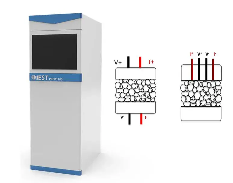
Figure 1. IEST PRCD3100 Powder Resistivity & Compaction Density Tester schematic and dual-module testing principles: four-probe resistance measurement (resistivity) and integrated thickness sensor (compaction density), operating pressure range 10–350 MPa (maximum 5T load)
Step 1 — Sample preparation. Six LMFP-NCM cathode blend compositions were prepared by physical mixing:
Step 2 — Resistivity and compaction density measurement. Within 10–350 MPa, each of the six blends was pressurized in 20 MPa step intervals. At each step, the PRCD3100’s four-probe resistance module and thickness module recorded resistivity and sample thickness simultaneously, yielding resistivity vs. pressure and compaction density vs. pressure curves for all six compositions.
Step 3 — Stress-strain measurement. Each blend was first pressurized from 10 MPa to 350 MPa in 20 MPa steps, then depressurized from 350 MPa back to 10 MPa in the same step interval, with continuous thickness recording throughout. This loading-unloading cycle produced the stress-strain curve for each blend, enabling extraction of maximum deformation, irreversible deformation, and reversible deformation (elastic rebound) at each LMFP-NCM ratio.
Figure 2 presents the resistivity (a) and compaction density (b) curves with applied pressure for all six LMFP-NCM blend cathodes.
Resistivity behavior (Figure 2a): Resistivity decreases monotonically with increasing pressure for all six blend compositions. This confirms that higher applied pressure improves inter-particle contact and reduces contact resistance, enhancing electron transport across the cathode powder bed. Critically, pure LMFP (100% LMFP) shows the highest resistivity across the entire 10–350 MPa range — confirming that the inherently low electronic conductivity of LMFP cathode powder is a limiting factor for rate performance. As NCM content increases, blend resistivity decreases progressively, approaching the electronic conductivity of pure NCM at high NCM fractions. This demonstrates that NCM addition can directly compensate for LMFP’s conductivity limitation through the percolation network formed between NCM particles in the blended electrode.
Compaction density behavior (Figure 2b): Compaction density increases with pressure for all blend compositions. Pure LMFP shows the lowest compaction density across all pressures. Continuous NCM addition progressively increases the compaction density of the hybrid cathode. This behavior arises from the combined effect of differing particle size distributions and mechanical properties: in a two-component particle system, smaller particles can fill interparticle voids of larger particles, reducing total void fraction; as pressure increases further, secondary particle cracking and crack propagation between particles further increase packing density. Higher compaction density at equivalent electrode thickness translates directly to higher volumetric energy density — a critical design parameter for high-energy-density EV batteries.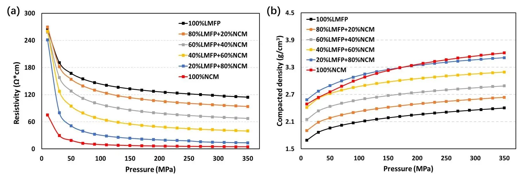
Figure 2. (a) Resistivity variation curves and (b) compaction density variation curves with pressure for six different ratios of LMFP and NCM hybrid cathode materials.
Figure 3(a) shows the loading-unloading stress-strain curves for all six blend compositions (10–350 MPa, 20 MPa step interval). A consistent observation across all six blends is that strain does not return to zero after depressurization — all tested LMFP-NCM cathode powders exhibit a non-negligible proportion of irreversible (plastic) deformation after the pressure cycle.
Figure 3(b) quantifies maximum deformation (black), irreversible deformation (orange), and reversible deformation (gray) as functions of NCM addition ratio. All three curves follow a U-shaped trend: both pure LMFP and pure NCM show larger total deformation than any of the four intermediate blend compositions. The minimum point for all three deformation metrics occurs at the 40% LMFP + 60% NCM composition — this blend exhibits the smallest total deformation, smallest irreversible deformation, and smallest reversible (elastic rebound) under the 350 MPa maximum pressure.
| LMFP-NCM Blend | Resistivity (relative) | Compaction Density (relative) | Total Deformation | Irreversible Deformation | Process Implication |
|---|---|---|---|---|---|
| 100% LMFP | Highest | Lowest | High | High | High conductivity additive loading required; large thickness rebound on roll-to-roll |
| 80% LMFP / 20% NCM | High | Low–Moderate | Moderate | Moderate | Improved vs. pure LMFP but conductivity still limited |
| 60% LMFP / 40% NCM | Moderate | Moderate | Low–Moderate | Low–Moderate | Good balance for safety-first applications |
| 40% LMFP / 60% NCM ★ | Moderate–Low | Moderate–High | Minimum | Minimum | Optimal mechanical behavior: most predictable electrode thickness after calendering |
| 20% LMFP / 80% NCM | Low | High | Moderate | Moderate | Good electrical properties; higher NCM cost |
| 100% NCM | Lowest | Highest | High | High | Best electrical performance; significant thickness rebound; safety considerations |
The practical implication for electrode manufacturing is significant: electrode thickness is a critical process control parameter during calendering. Minimizing post-calendering thickness rebound improves thickness uniformity and reduces the risk of capacity variance across a production batch. The stress-strain data from Figure 3 show that different LMFP-NCM blend ratios require different calender gap settings and pressure profiles to achieve target electrode thickness — and the 40% LMFP + 60% NCM composition offers the most favorable mechanical response for thickness control.
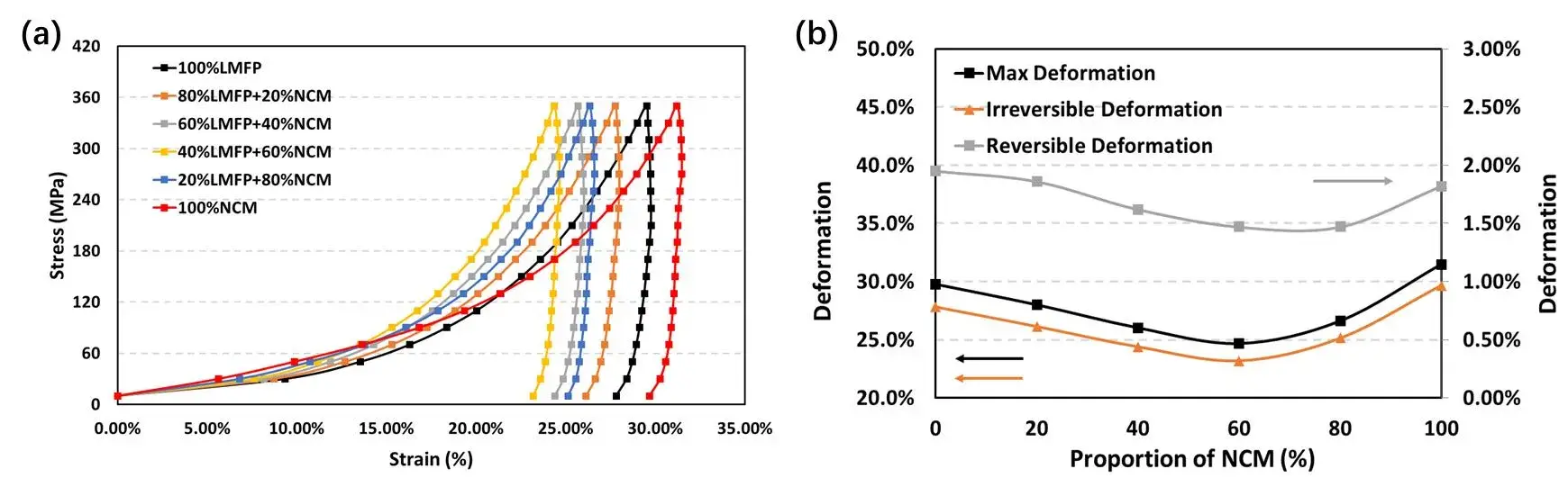
Figure 3. (a) Stress-strain curves for six LMFP-NCM hybrid cathodes during pressurization and depressurization (10–350 MPa, 20 MPa step interval). (b) Maximum deformation (black), irreversible deformation (orange), and reversible deformation (gray) vs. NCM addition ratio — the 40% LMFP + 60% NCM blend shows minimum values at the U-curve inflection point
Liebmann et al. conducted a systematic study on how the electrochemical properties of individual components influence the behavior of blended cathodes for LFP, NCM, and LMO systems.[4] Their findings establish an important boundary condition for interpreting the present LMFP-NCM data:
This distinction is directly relevant to the LMFP-NCM system: the resistivity and compaction density improvements observed with NCM addition can be partially predicted from the component properties, but the optimal blend ratio for rate performance and cycle life requires full-cell testing to capture the kinetic dimension that powder-level characterization alone cannot resolve.
The IEST PRCD3100 applies 10–350 MPa (up to 5T) in programmable 20 MPa steps, simultaneously recording four-probe resistivity and compaction density in a single pressurization cycle — providing the synchronized electrical and mechanical characterization data needed to screen LMFP, NCM, LFP, and hybrid cathode powders before electrode fabrication.
This study used the IEST PRCD3100 Powder Resistivity & Compaction Density Tester to characterize six LMFP-NCM hybrid cathode blends across 10–350 MPa. The key findings are:
The parameters characterized in this study — resistivity, compaction density, and stress-strain response — are necessary but not sufficient for final blend ratio selection. Cycle performance, rate capability, temperature performance, and cost must be evaluated at the full-cell level before the optimal blending ratio is determined for a specific application.
[1] T. Or, S.W.D. Gourley, K. Kaliyappan, A.P. Yu and Z.W. Chen, “Recycling of mixed cathode lithium‐ion batteries for electric vehicles: Current status and future outlook.” Carbon Energy 2 (2020) 6–43.
[2] H.S. Kim, S.I. Kim and W.S. Kim, “A study on electrochemical characteristics of LiCoO₂/LiNi₁/₃Mn₁/₃Co₁/₃O₂ mixed cathode for Li secondary battery.” Electrochimica Acta 52 (2006) 1457–1461.
[3] X.X. Zhao, L.W. An, J.C. Sun and G.C. Liang, “LiNi₀.₅Co₀.₂Mn₀.₃O₂–LiMn₀.₆Fe₀.₄PO₄ mixture with both excellent electrochemical performance and low cost as cathode material for power lithium ion batteries.” Journal of Electrochemical Society 165 (2018) A142–A148.
[4] T. Liebmann, C. Heubner, M. Schneider and A. Michaelis, “Understanding kinetic and thermodynamic properties of blended cathode materials for lithium-ion batteries.” Materials Today Energy 22 (2021) 100845.
LMFP stands for lithium manganese iron phosphate (LiMnxFe1-xPO4). LMFP cathode is a phosphate-based lithium-ion battery cathode material derived from LFP (lithium iron phosphate) in which manganese partially replaces iron. The manganese doping raises the average operating voltage from LFP’s ~3.4 V to approximately 4.1 V, increasing theoretical energy density by 15–20% compared to LFP while maintaining the olivine structure’s inherent chemical stability and thermal safety — making LMFP cathode a leading candidate for next-generation cost-competitive, high-safety EV batteries.
LMFP cathode shows a two-plateau discharge voltage profile: a higher-voltage plateau near 4.1 V (corresponding to the Mn²⁺/Mn³⁺ redox reaction) and a lower-voltage plateau near 3.4 V (corresponding to Fe²⁺/Fe³⁺, identical to LFP). LFP shows only the single Fe²⁺/Fe³⁺ plateau at ~3.4 V. The Mn-based plateau at 4.1 V is responsible for LMFP’s energy density advantage over LFP. A known challenge with LMFP is “voltage jump” behavior at the transition between the two plateaus, which is an active area of material engineering research.
LMFP cathode powder has inherently low electronic conductivity — the highest resistivity among common cathode materials. In LMFP-NCM blends, NCM particles form conductive percolation networks between LMFP particles, progressively reducing blend resistivity as NCM content increases from 0% to 100%. IEST PRCD3100 measurements across 10–350 MPa confirm a monotonic resistivity reduction with increasing NCM fraction across all tested pressures. However, resistivity measured at the powder level does not fully predict rate performance at the electrode level, where conductive additive loading and binder distribution also play important roles.
Stress-strain measurements on six LMFP-NCM blends (0–100% NCM, 10–350 MPa loading-unloading cycles) show that all three deformation metrics — maximum deformation, irreversible deformation, and reversible deformation — follow a U-shaped trend with NCM content. The minimum for all three occurs at the 40% LMFP + 60% NCM blend. This composition shows the smallest post-calendering thickness rebound among all tested ratios, which is the most favorable behavior for achieving consistent electrode thickness in roll-to-roll manufacturing. Note that optimal blend ratio for a given application must also account for cycle life, rate performance, safety, and cost — parameters that require full-cell characterization beyond powder-level testing.
LFP cathode is known for exceptional cycle life, routinely exceeding 2,000–3,000 charge-discharge cycles at standard conditions. LMFP cathode cycle life has historically lagged behind LFP due to manganese dissolution at the cathode surface, Jahn-Teller distortion in Mn³⁺ particles, and voltage jump behavior that creates mechanical stress. Recent engineering advances — including carbon coating, particle morphology control, and electrolyte additive optimization — have substantially improved LMFP cycle life, with commercial-grade LMFP cathode materials now targeting >2,000 cycles. Blending LMFP with NCM can further modulate cycle life depending on the NCM content, requiring full-cell evaluation for each target application.
The IEST PRCD3100 is a Powder Resistivity & Compaction Density Tester that simultaneously measures resistivity (via four-probe method) and compaction density (via integrated thickness sensor) of battery electrode powders under applied pressure. The instrument operates from 10 MPa to 350 MPa (maximum 5T load) with programmable step intervals (typically 20 MPa), and can also perform loading-unloading cycles to generate stress-strain curves for mechanical property characterization. The PRCD3100 is applicable to cathode materials including LFP, LMFP, NCM, LCO, and NCA, as well as anode materials such as graphite and silicon-carbon composites.
