

In battery research and development, electrode flexibility is a critical performance indicator. It acts like the “skeletal resilience” of a battery, requiring sufficient strength to support volume changes during charge/discharge cycles, along with good ductility to withstand repeated mechanical stresses. Numerous methods exist for assessing electrode flexibility. Different manufacturers may adopt various approaches based on product specifics and testing needs, such as manual folding over a roller to check light transmission, wrapping around a needle to observe active material shedding, or three-point bending tests.
However, these manual methods depend heavily on operator subjective judgment — for example, visually inspecting for active material shedding — rather than continuous, quantifiable mechanical parameters. This dependence on subjective assessment leads to significant test errors, poor batch-to-batch and operator-to-operator consistency, and limited information depth for engineering decision-making.
IEST Electrode Flexibility Testing System (BEF1000) employs a different methodology. This device clamps the electrode strip and bends it at a specific angle within a fixture. A controlled displacement is then applied to deform the electrode, and the resulting force-displacement curve is measured continuously. By analyzing this force-displacement relationship, the electrode flexibility of different samples can be precisely quantified and compared. Notably, cathode and anode materials exhibit substantially different mechanical behaviors, typically necessitating distinct testing and analysis strategies:
Cathode: Evaluated for bendability via single-cycle compression.
Anode: Evaluated for recoverability via cyclic testing.
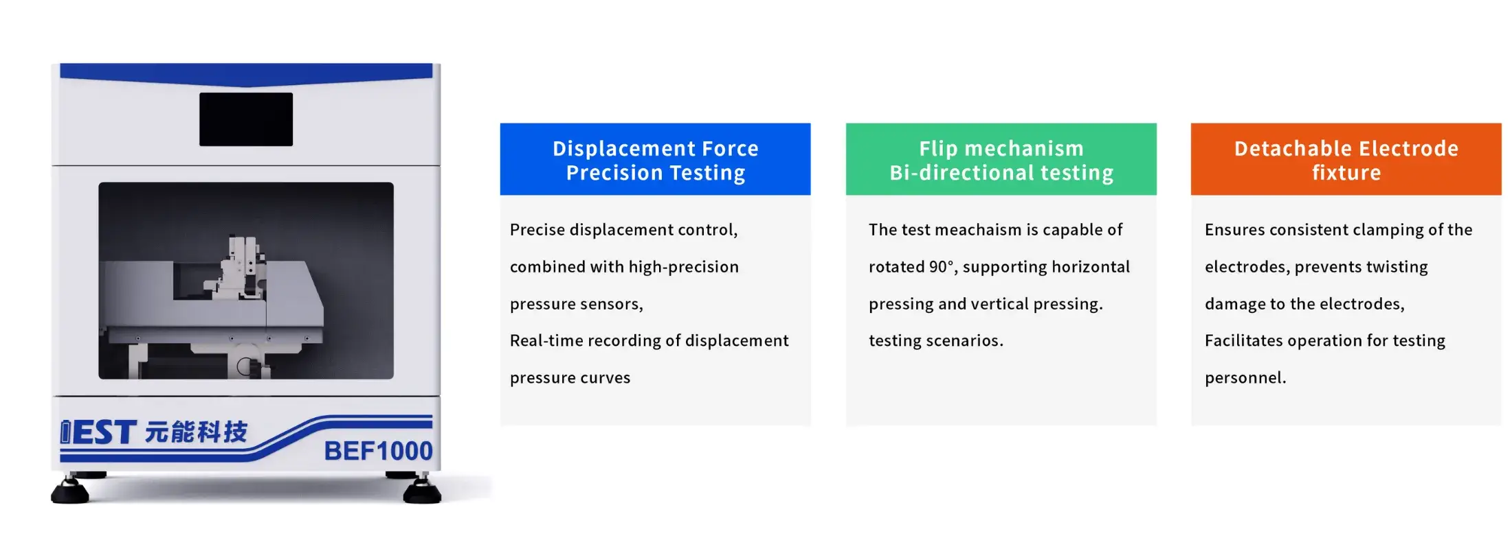
Figure 1. IEST Battery Electrode Flexibility Testing System (BEF1000) Equipment
Cathode electrodes are generally more brittle, often exhibiting coating cracking during testing. Therefore, a single-cycle, constant-speed test mode is typically employed. The resulting force-displacement curve is analyzed to evaluate the cathode’s bendability, a key aspect of its flexibility.
Figure 2 shows test data for two LFP cathodes with different compaction densities. Both curves exhibit a sudden drop or inflection point, indicating a release of stress. This stress release primarily originates from cracking within the electrode coating. Generally, a shorter displacement to fracture indicates poorer bendability and, consequently, inferior flexibility.
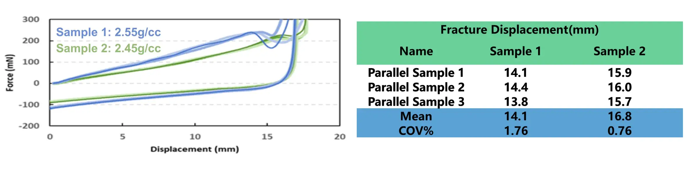
Figure 2. Force-Displacement Curves for Cathodes with Different Compaction Densities
When the fracture displacements of two samples are similar, how can we further differentiate them? Parameters like fracture force and curve slope become crucial. As shown in Figure 3, under the same applied displacement, a higher measured force indicates greater resistance to bending deformation — meaning the electrode is “stiffer.” But does a stiffer electrode automatically mean worse flexibility?
Stiffness reflects a material’s resistance to localized deformation, while flexibility describes its ability to deform before fracture. These properties are governed by different factors and may not always trend together. Typically, electrode stiffness and flexibility show a negative correlation. A stiffer electrode (e.g., due to high active material content, high compaction density, low or inherently stiff binder content) often tends to be more brittle, cracking or shedding more easily during bending, winding, or impact. However, the strength and direction of this correlation are complex, influenced by a combination of factors including binder properties, active material, conductive additives, compaction density, porosity, and microstructure.
Beyond fracture displacement and force, two additional analytical signals refine bendability assessment:
Curve shape: electrodes with higher flexibility tend to produce smoother force-displacement curves, without abrupt discontinuities.
First derivative (dF/dS): electrode sheets with poorer flexibility typically show larger peaks or sharper changes in the first derivative of the force-displacement curve, providing a more sensitive indicator of the fracture onset than the raw curve alone.
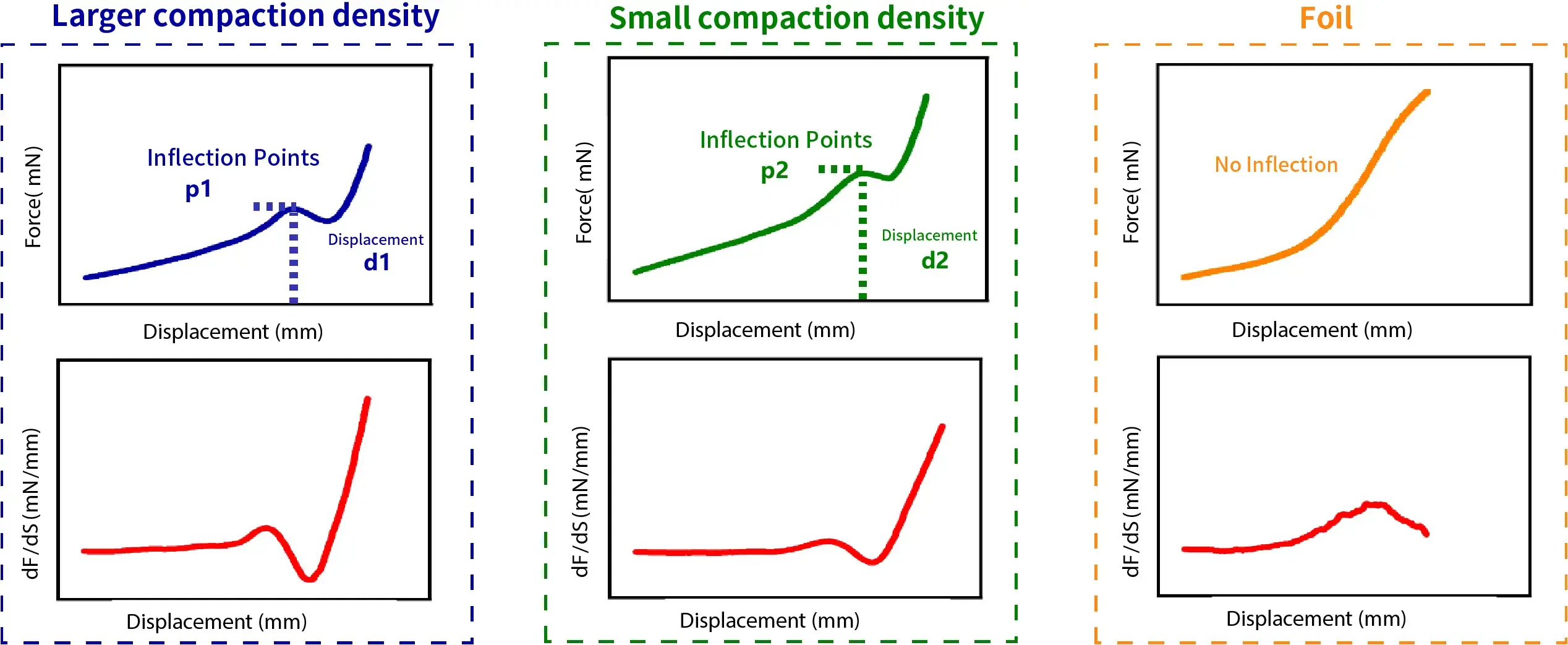
Figure 3. BEF1000 bendability analysis — force-displacement and first-derivative (dF/dS) curves for larger compaction density, small compaction density, and foil samples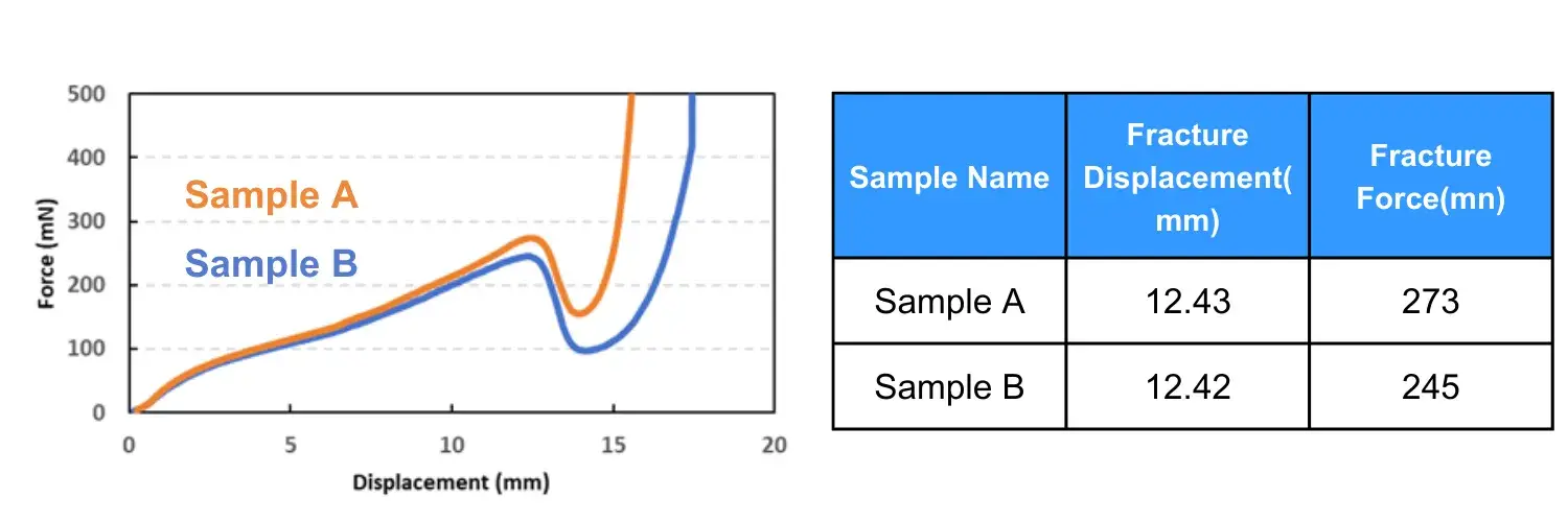
Figure 4. Force-Displacement Curves for Sample A and Sample B
Compared to cathodes, anode electrodes are typically softer and may not show obvious coating cracking during a single bending test. Thus, analysis focuses on a different dimension: the electrode’s recoverability (its ability to return to its original shape after the removal of an external force).
The BEF1000 device can perform cyclic (to-and-fro) bending tests. The “residual stress” measured upon returning to the starting point serves as a key metric for evaluating recoverability. The origin of this residual stress is as follows: the force sensor is zeroed before the test begins. During the cyclic bending, energy is dissipated due to irreversible deformation within the electrode structure. Consequently, when the probe returns to its initial position, the force measured deviates from zero. This non-zero force value is termed the “residual stress.” A larger absolute value of residual stress indicates greater energy loss (more irreversible damage) during cycling, signifying poorer recoverability and thus inferior flexibility.
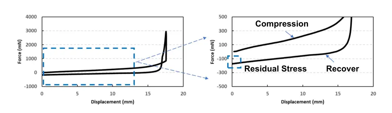
Figure 5. Schematic of Residual Stress Analysis
Figure 6 shows data for two anode electrodes containing different binders. Reciprocating tests yielded their residual stresses. The results indicate that Sample 1 exhibited a residual stress closer to the initial value (zero) after one reciprocating cycle. This suggests less irreversible damage occurred during testing, indicating superior recoverability and, consequently, better flexibility for Sample 1. Furthermore, the IEST BEF1000 can perform multi-cycle reciprocating tests to observe electrode fatigue results, please check article: Electrode Fatigue Testing | Evaluation of Anode Electrode Recoverability
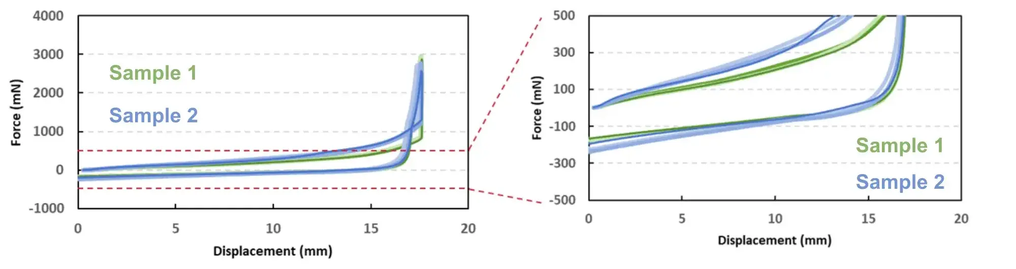
Figure 6. Reciprocating test results for two anode electrodes, measured by IEST BEF1000
| Parallel Time | Sample 1 | Sample 2 |
|---|---|---|
| 1 | -167.0 | -219.0 |
| 2 | -172.0 | -230.0 |
| 3 | -165.0 | -200.0 |
| Mean | -168.0 | -216.3 |
| COV% | -1.75 | -5.73 |
Manual folding, needle-wrapping, and basic three-point bending remain common in the industry precisely because they require no specialized equipment — but that convenience comes at the cost of data an engineering team can actually use for formulation comparison, quality control, or root-cause analysis. The table below summarizes the practical gap between conventional manual inspection and quantitative testing on the BEF1000.
| Testing Aspect | Traditional Manual Method | IEST BEF1000 | Engineering Value |
|---|---|---|---|
| Endpoint definition | Visual judgment of coating shedding or cracking | Force drop / inflection point on a continuous force–displacement curve | Removes operator subjectivity; enables a defined, repeatable fracture criterion |
| Data output | Pass / fail impression | Force–displacement curve, fracture displacement, fracture force, dF/dS derivative | Quantifiable parameters for formulation and compaction-density comparison |
| Cathode evaluation | Fold or wrap and inspect for shedding | Single-cycle constant-speed bending with fracture-point analysis | Distinguishes bendability differences even when fracture displacement is similar |
| Anode evaluation | Not typically differentiated from cathode inspection | Cyclic bending with residual-stress measurement | Quantifies recoverability and fatigue behavior that visual inspection cannot detect |
| Repeatability | Poor batch-to-batch and operator-to-operator consistency | Parallel-run COV% as low as 1.75% (Table 1) | Statistically defensible data for R&D reports and supplier qualification |
Formulation and process engineers evaluating a new binder, a higher compaction density, or a different active-material loading need to know, in numbers, whether the change makes the electrode more prone to cracking during winding or more likely to lose contact after cycling — not just whether a technician’s visual check passed. Without a continuous mechanical signal, flexibility problems typically surface downstream, during winding yield loss or post-cycling capacity fade, where they are far more expensive to diagnose and trace back to a specific formulation change.
The IEST BEF1000 addresses this by converting a subjective pass/fail inspection into a controlled, repeatable mechanical measurement — fracture displacement and force for cathode bendability, residual stress for anode recoverability — that can be compared directly across formulations, suppliers, and production batches.
IEST BEF1000: controlled-angle bending fixture · continuous force–displacement measurement · single-cycle bendability mode for cathodes · cyclic recoverability mode for anodes · dF/dS derivative analysis for early fracture detection.
Explore the BEF1000 Battery Electrode Flexibility Testing System →
Electrode flexibility remains hidden inside the finished battery, but it is a critical determinant of manufacturing yield and long-term product competitiveness. Selecting the correct testing mode based on the force–displacement curve characteristics and the physical failure behavior of the electrode — single-cycle bendability analysis for brittle cathodes, cyclic recoverability analysis for ductile anodes — allows engineers to move from subjective visual inspection to scientific, quantifiable electrode flexibility testing. Through this data, formulation teams can give each electrode enough mechanical resilience to travel farther and endure longer.
Battery electrode flexibility is a coated electrode’s ability to withstand bending and cyclic deformation — the stresses imposed during winding, stacking, and charge–discharge cycling — without coating fracture, active material shedding, or loss of contact with the current collector. It is measured as bendability for cathodes and recoverability for anodes, both quantified from a continuous force–displacement curve.
Electrode bendability describes a cathode’s resistance to coating fracture under a single bending event, quantified by fracture displacement and fracture force. Electrode recoverability describes an anode’s ability to return to its original shape after repeated bending, quantified by residual stress measured when the probe returns to zero. Cathodes are typically evaluated for bendability; anodes are typically evaluated for recoverability.
Selecting an electrode flexibility testing system depends on whether the target material fails by fracture (cathodes, requiring single-cycle bending with fracture-point detection) or by fatigue (anodes, requiring cyclic bending with residual-stress measurement). IEST Instrument’s BEF1000 supports both single-cycle and multi-cycle reciprocating test modes in one fixture, addressing both failure mechanisms without switching instruments.
There is no single universal threshold; residual stress is a comparative metric read against a baseline or reference sample rather than an absolute pass/fail number. In the BEF1000 data referenced here, a sample with a residual stress closer to zero (for example, -168.0 mN mean) demonstrated better recoverability than a sample further from zero (-216.3 mN mean), indicating less irreversible deformation during cycling.
During single-cycle bending, coating cracking releases stored mechanical stress within the electrode coating, which appears as a sudden force drop or inflection point on the force–displacement curve. The displacement at which this drop occurs is the fracture displacement; the first derivative (dF/dS) of the curve provides an even more sensitive indicator of the fracture onset than the raw curve alone.
