-
iestinstrument
Evaluation Scheme Of Electrical and Mechanical Properties of Composite Current Collectors
1. Composite Fluid Technology Background
Composite current collector is a “sandwich” structure, the inner polymer polymer layer (such as PET, PP or PI), both sides of the metal conductive layer (such as Al or Cu), such as Figure 1 for the composite collector structure schematic. The current industrial mass production of composite collectors in the composite copper foil collector using 4.5μm OPP (polypropylene) as a substrate, first in the substrate on both sides of the magnetron sputtering each 50nm copper layer, and then in the copper layer on the surface of the aqueous plating, thickening the copper layer to about 1μm. The composite aluminum foil collector usually uses 6μm PET (polyethylene terephthalate) as the substrate, and then 1μm aluminum layer is vapor-deposited on both sides of the substrate. The structure of the composite current collector is shown schematically in Figure 1.
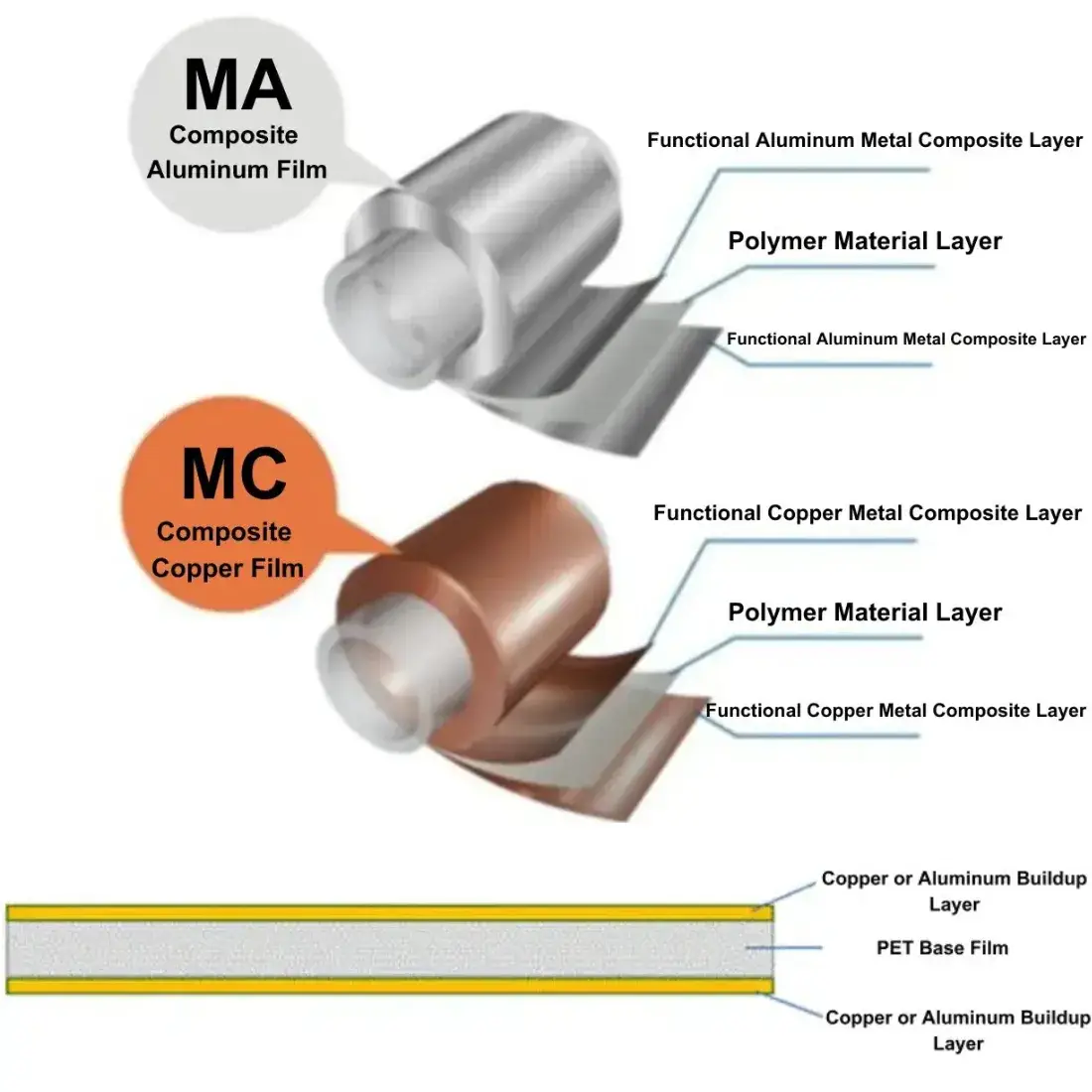
Figure 1. Schematic diagram of the structure of the composite current collector
2. Composite current collectors vs. conventional fluid collectors
2.1 Advantage
Compared to traditional copper and aluminum foils, the composite material of copper and aluminum foils brings two benefits: safety and cost.
2.2 Safety Benefits
Compared to traditional single collectors, the base film material in the center of the composite collector acts like a fuse, which can quickly break or melt when it encounters a short-circuit failure mode, thus blocking further conduction of current and ultimately preventing the battery cell from burning.
2.3 Cost Benefit
The supply price of battery copper foil has remained tight in 2021, with a long expansion cycle and a gap in market demand. The current copper foil composite current collector has a high manufacturing cost, and the price is not advantageous compared with single material copper foil. But later if the scale after the cost is expected to be reduced. In addition to the BOM cost is less, copper foil composite current brings another benefit because the weight reduction makes the battery mass energy density increase. In addition, aluminum foil composite current collector cost advantage is more obvious, aluminum foil composite current collector thickness is only half of the thickness of a single aluminum foil, composite aluminum foil collector because of the thinning of the battery volume energy density increase.
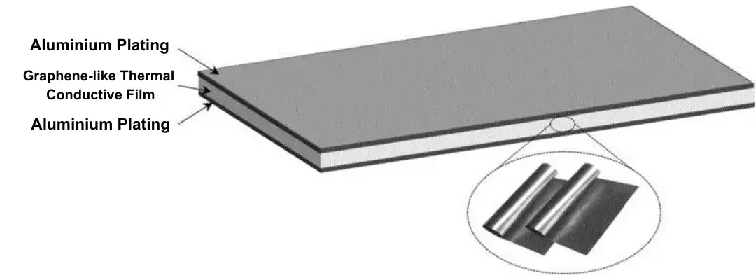
Figure 2. Schematic diagram of aluminum foil composite current collector
2.4 Disadvantage
Composite current collectors have the following disadvantages compared to conventional fluid collectors:
2.5 Foil perforation
The metal may splash and melt through the foil to form through holes during magnetization and vaporization into the PET material because of the high temperature of the molten metal.
2.6 Capacity bottleneck
Due to the limitations of the magnetization and vaporization of the beat, the unit equipment efficiency of the composite foil is not as good as that of the traditional foil, which will be an obvious bottleneck in the process of product release.
The internal resistance of the battery increases, and the output power of the battery is affected. Compared to metal foil, composite foil PET is not conductive, the thickness of the conductive metal layer is significantly lower, there is a larger electronic resistance, and at the same time, due to the introduction of flame retardants and other media, the battery resistance will increase.
2.7 Battery manufacturing requires new processes
Because of the introduction of PET material, the conventional battery production process can not be directly panned. At least one additional transfer welding process is required to make the tabs for the electrodes in the electrode fabrication process, and the manufacturing cost of the battery increases.
3. Evaluation of the Electrical Properties Of Composite Current Collectors
The main reasons for the higher resistivity of the battery electrode composite current collector compared to the conventional collector may be the following:
3.1 Materials Selection
Battery electrode composite current collectors are usually constructed using a composite of multiple materials, which may not have as excellent electrical conductivity as a single material in a conventional collector, resulting in an overall higher resistivity.
3.2 Structural design
The structural design of the composite current collector for the battery electrode may be complex, for example, in order to improve the mechanical strength or other characteristics of the collector, some insulating properties may be added to the material, thus increasing the resistivity.
3.3 Manufacturing process
The manufacturing process of the composite collector may be relatively complex, making it difficult to ensure the uniformity and consistency of each part, resulting in an uneven distribution of resistivity.
4. Electrical Experiment Program Design
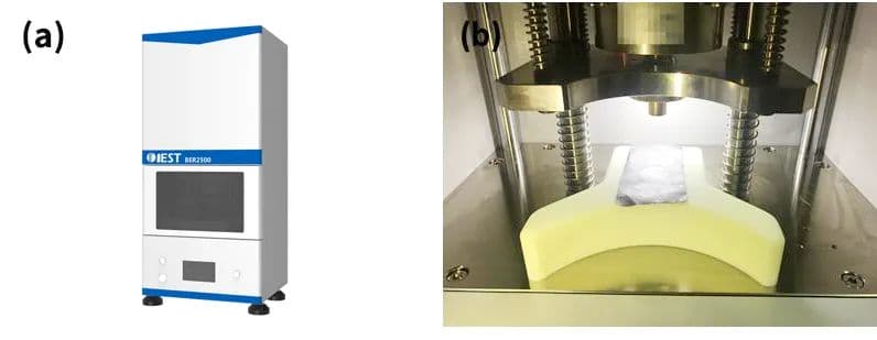
Experimental instrument: model BER2500 (IEST), electrode diameter 14mm, the equipment is shown in Figure 3(a) and 3(b).
Figure 3. Schematic diagram of the appearance and structure of the BER2500
Place the conventional current collector and composite current collector to be tested between the two electrodes of the electrode resistivity meter, set the test pressure of 5MPa on the MRMS software, the holding time of 15s, and start the test. The software automatically reads the data of electrode thickness, resistance, resistivity and conductivity.
5. Data Analysis
The results of testing the thickness and resistivity of the composite current collector show that the thickness of the composite current collector selected in this experiment is smaller than that of the traditional collector, of which the thickness of the copper foil composite current collector is the smallest. The longitudinal penetration resistivity of the composite current collector is much higher than that of the traditional collector, in which the resistivity of the aluminum foil composite current collector is the largest, which is one order of magnitude higher than that of the copper foil collector, which is mainly due to the fact that the intermediate layer of the “sandwich” structure is mostly a polymer polymer layer with low conductivity.

Figure 4. Resistivity and thickness test data for four different collectors
6. Evaluation of mechanical properties of composite current collector
Mechanical test program: four types of collectors of the same size 2cm x 3cm were cut and fixed in the same position. The ultimate mechanical properties of the different collectors were tested using a steel needle under pressure at a constant rate. The test results are as follows.
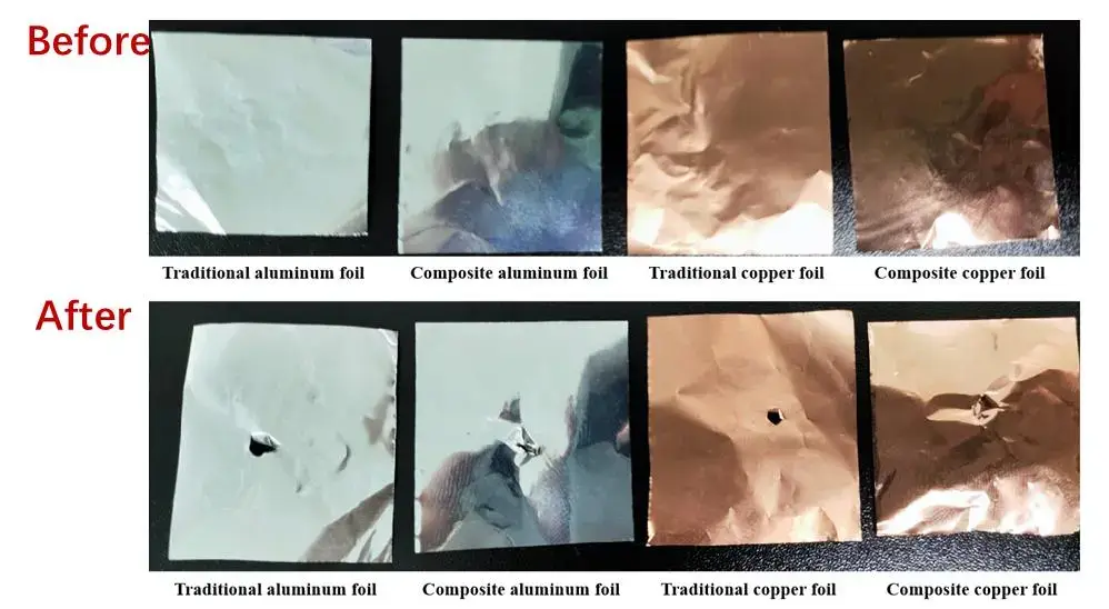
Figure 5. Comparison of the results of needle puncture experiments with four types of current collectors
The results of the pinning experiments show that the strength of the aluminum foil composite current collector per unit thickness is significantly improved compared to the conventional aluminum foil collector, while the strength of the copper composite current foil collector per unit thickness is slightly improved compared to the conventional collector.
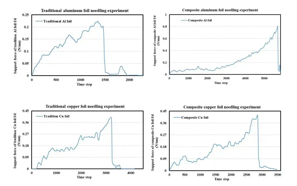
Figure 6. Comparison of experimental data from needle puncture experiments with four types of current collectors
7. Summary
It is reported that the composite current collector industry is in the stage of importing from the validation period to the mass production period, with the outstanding advantages of high safety, high specific energy, low cost, long life, strong compatibility and so on, the industrialization of composite current collector is further enhanced. However, it must be recognized that the long-term penetration of composite current collector still need to look at process improvement and cost reduction progress. One of the conductive properties, after the composite current collector electronic conductivity deterioration, thermal conductivity deterioration; it will directly affect the final battery electrical performance. However, from a safety point of view, after the composite current collector mechanical strength has been improved, can effectively reduce the traditional collector fluid may bring some security risks, the overall enhancement of the battery in the use of the process of safety.
8. References
[1] WANG Ru, LIU Zhikang, YAN Chao, et al. Interface Strengthening of Composite Current Collectors for High-Safety Lithium-Ion Batteries [J]. Journal of Physical Chemistry, 2023, 39(2):81-92.
[2] LIU Song; HOU Hongying; HU Wen; LIU Xianxi; DUAN Jixiang; MENG Ruijin. Research Progress of Current Collectors for Li-ion Batteries [J]. Silicate Bulletin, 2015, 34(9):2562-2568.
[3] WANG Chenghao,LI Xuefa,ZHANG Guoping. Aluminum composite current collector and its preparation method, positive electrode sheet, battery and electric device:CN202210827592.9[P1.CN202210827592.9[2023-10-071.
[4] WANG Shuai, ZHU Ya Ya, XIA Jianzhong, et al. A composite current collector soft pack battery case, soft pack battery and soft pack battery module:CN202211623631.X[P].CN116169403A[2023-10-07].
Subscribe Us
Contact Us
If you are interested in our products and want to know more details, please leave a message here, we will reply you as soon as we can.


