-
iestinstrument
Characterization Method Of Expansion Force Of Cylindrical Cells
1. Preface
There are three main encapsulation forms for lithium batteries, namely pouch cell, prismatic cell and cylindrical cell. pouch cells use aluminum-plastic film as the encapsulation material, which provides design flexibility and a variety of models, and the shape can be customized according to customer needs. Pouch cells have low internal resistance and high energy density, and they usually inflate and crack when they fail. However, pouch cells suffer from poor consistency and are prone to leakage. Prismatic cells usually use aluminum alloy, stainless steel and other materials as the shell, which have high structural strength and good ability to withstand mechanical loads. Prismatic cells have a simple group structure and relatively high system energy density. However, the stainless steel material can lead to a heavy weight of the cell, which affects the energy density. In addition, the production process of prismatic cells is more complicated, and the yield rate and consistency are not as good as that of cylindrical cells. Cylindrical cells have a long history and high market penetration, and use a fairly mature winding process with a high degree of automation, consistent quality and relatively low cost.
At present, for evaluating the expansion performance of battery cells, prismatic cell and pouch cells can already be characterized by corresponding methods to characterize their expansion behavior. However, due to the specificity of the structure of cylindrical cells themselves, the expansion characterization method has not been clearly determined. Therefore, the aim of this paper is to calculate the expansion characteristics of cylindrical cells through mathematical theory and provide a characterization method to describe the expansion force of cylindrical cells.
2. Test Information
2.1 Experimental equipment
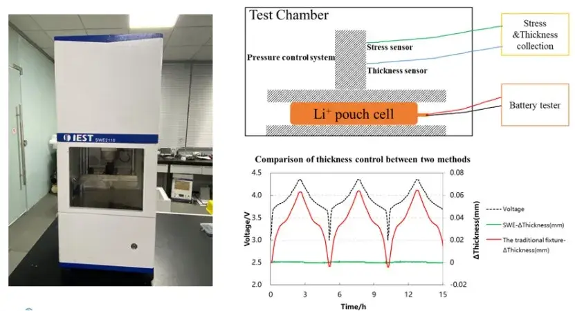
In-situ Swelling Testing System, Model SWE2100 (IEST), as shown below:
Figure 1. Schematic diagram of the in-situ swelling testing system(SWE2100)
3. Result Analysis
3.1 Expansion analysis of cylindrical cell
The stress analysis of the cylindrical shell is shown in Figure 2 as follows: under the action of internal pressure pi, each cell will be subjected to three stresses, σa is the axial stress along the height of the cylinder, which comes from the end face of the two ends of the cylinder and causes the change of the height of the cylinder, σr is the radial stress perpendicular to the surface of the cylinder, which is outward along the direction of the diameter, and it has a tendency to cause outward deformation of the surface of the shell,and σt is the circumferential stress along the circumference of the cylinder, which will cause changes of the perimeter of the shell, while σt is the annular stress along the circumference of the cylinder. Therefore, both σr and σt are the causes of shell expansion.
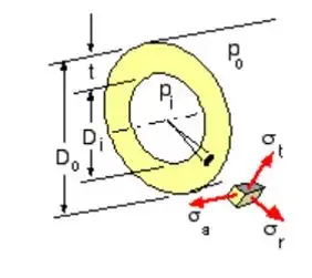
Figure 2. Cylindrical cell shell stress decomposition
In accordance with the thick-walled cylinder shear stress theory to derive the three stresses expressed as follows ① ② ③. Take 3665 cell as an example: inner diameter ri is 17.7mm, outer diameter r0 is 18.0mm, P0 is 0.1MPa at atmospheric pressure, assuming that the internal pressure Pi is 1.0MPa, the calculation shows that σr is -0.1MPa, σt is 52.6MPa and σa is 26.2MPa, which means that the expansion of the cell is mainly due to axial and circumferential stresses.
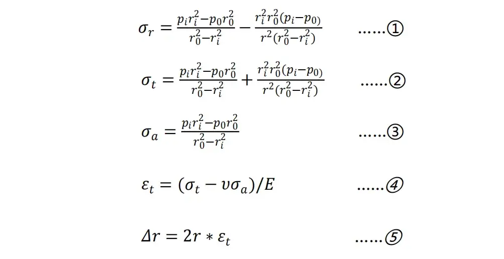
Figure 3. Calculation Formula
Ignoring the influence of σr, the change in shell diameter can be obtained by further combining the stress-strain law of the steel shell (Formula ④) and the circumference formula (Formula ⑤). Assuming that the elastic modulus E of the steel material is 210GPa and the Poisson’s ratio υ is 0.3, it is calculated that the radial expansion is about 9.4μm when fully charged (assuming that the internal pressure P1 is 1.2MPa at this time). If it returns to the state after being fully discharged, that is, the internal pressure is 1.0MPa, the radial expansion is 7.7μm at this time, and the radial expansion thickness during the charging and discharging of the battery cell is about 1.7μm. The calculation of the charging and discharging deformation of different types of battery cells under this condition and this method is shown in Table 1 below. It can be obtained that there is basically no radial expansion of the cylindrical battery cell during the charging and discharging process. In practice, the internal pressure after formation may not reach 1.0MPa, and some processes are formed first and then sealed, which also shows that the actual deformation will be smaller than the calculated value in Table 1.
Table 1. Radial calculation of charge and discharge of different types of batteries

Thickness variations are particularly pronounced in flexible cells with flexible aluminum-plastic films, and measurements are easily achieved. However, due to the structural rigidity of the hardshell body, cylindrical cells exhibit much smaller diameter expansion (~0.1%), making it difficult to observe reversible and irreversible cell diameter changes. However, due to the growth of irreversible layer thicknesses such as the solid electrolyte interface (SEI) layer and Li plating, which can lead to volume changes, and gassing due to side reactions, which can also lead to an increase in pressure inside the shell, the cells inside the shell will definitely expand and contract during charging and discharging. In order to understand what potential mechanical processes are occurring inside the battery, suitable measurements are needed to record and analyze parameters such as electrode thickness and volume changes of the cell components. Evaluating the structural characteristics of a cell typically uses methods such as X-rays, computed tomography, neutron and ultrasound imaging to obtain comprehensive information on strain, stress distribution and structural strength. While these techniques are powerful, they are often used as offline diagnostic techniques due to the need for special equipment, high cost, and the inevitable interference these high energy sources cause during battery operation.
3.2 Characterization of the expansion force of cylindrical cells
Given that cylindrical cells are essentially non-expanding in the radial direction, they cannot be monitored directly from the outside of the cell. The expansion changes in Table 1 are comparable to the controlled fluctuations of ±1μm in the constant gap mode of IEST in-situ swelling analysis system (SWE2100), so the SWE2100 equipment can be used to simulate the binding of the cylindrical cell shell on the core, thus realizing the characterization of the expansion force of the cylindrical cell. The pre-testing process is shown in Figure 4 below: in a glove box or dry room, the outer package (steel shell) is removed, then the tabs are extended, and finally the package is re-encapsulated with aluminum-plastic film.
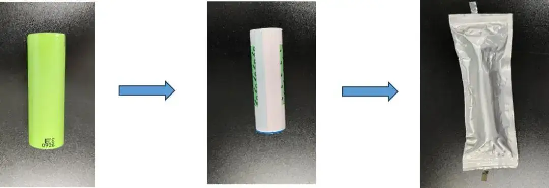
Figure 4. Pre-treatment flow of cylindrical cell
During the test, the cell was directly placed in the test chamber (between two ceramic plates), and the test software (MISS2.1) was turned on, and the constant gap mode was selected to monitor the expansion force with the change of SOC in situ, as shown in Figure 5 below.

Figure 5. Expansion force of cylindrical cells of different models
The main thing that this method monitors is the deformation process of the cylindrical cell during the charging and discharging process. As shown in Figure 6, cylindrical cells, unlike flexible aluminum-plastic film shells of soft-pack batteries, have rigid metal shells, which can impede the release of stresses generated by internal expansion. The non-uniform contact between the metal shell and the internal film in the tested battery leads to tiny loose contacts, which results in uneven stress distribution. In the early stages of cycling (i.e., new batteries), the volume expansion mechanism is shown in Figure 6a. The surface of the cell is initially relatively circular, and the stress distribution inside the cell is transferred to the metal case when the cell is fully charged, thus creating a non-uniform expansion distribution. Due to the structure of the cell roll, the radially protruding expansion results in shrinkage depressions on the metal case. As cycling proceeds, the increase in irreversible expansion causes this peak-valley structure to be permanently fixed and accumulated, bringing the case into closer contact with the interior, as shown in Figure 6b.
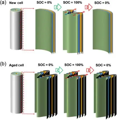
Figure 56. Schematic diagram of the mechanism of volume change of new (a) and aged (b) cylindrical cells
4. Summary
In this paper, the in-situ swelling analysis system (SWE2100) constant gap mode analog shells are used to bind cylindrical cells, so as to realize the in-situ characterization of the expansion force of cylindrical cells, and help the optimization and development of cylindrical cells. It can also be explored to provide an expansion optimization strategy for high expansion materials such as silicon anode by taking advantage of the cylindrical structure.
5. References
W.X. Jiang, H.R. Li, S.C. Wang, S.S. Wang, W. Wang, Dynamic Volume Imaging by Observing the Breathing of Cylindrical Lithium-Ion Batteries during Cycling,
Subscribe Us
Contact Us
If you are interested in our products and want to know more details, please leave a message here, we will reply you as soon as we can.


