-
iestinstrument

Abstract
1. Introduction
Traditional constant-gap testing uses a steel plate pouch cell pressure fixture that clamps the cell between pressure plates using bolts and monitors force via a load cell on the upper plate. This method cannot guarantee a constant gap between platens during cycling — the gap fluctuates by tens to hundreds of microns as the cell expands and contracts. As shown in Figure 1, the traditional fixture gap fluctuates by approximately 65 µm during charge/discharge (red curve). This drift makes accurate cell gap measurement and repeatable expansion analysis impossible with bolt-fixed setups.
A second traditional approach — placing a fixed weight on the cell surface — provides approximate constant-pressure conditions but offers no way to freely adjust target pressure or perform automated cell gap measurement 4-7. The IEST SWE2110 solves both limitations through an automatic pressure-and-displacement control system, enabling true Constant Pressure and Constant Gap test modes with near-zero gap drift (green curve, Figure 1).

Figure 1. Thickness control comparison between traditional pouch cell pressure fixture and SWE test system in constant-gap mode — demonstrating ±65 µm drift vs near-zero gap variation.

Figure 2. Schematic diagram of in-situ swelling test system (SWE) structure.
2. Experimental Equipment and Test Methods
2.1 Experimental Equipment
All tests were conducted on the IEST SWE2110 In-Situ Swelling Analyzer (Figure 3). The SWE2110 integrates a high-precision displacement actuator, load cell, environmental control, and synchronized electrochemical cycler. It supports both Constant Pressure and Constant Gap modes, and logs cell thickness, expansion thickness change, force/pressure, temperature, current, voltage, and capacity simultaneously — enabling reliable battery design pressure measurement and expansion analysis in a single automated test.
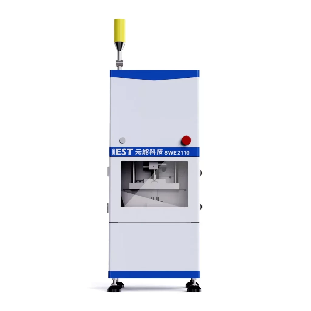
Figure 3. Appearance of the IEST SWE2110 In-Situ Swelling Analyzer.
2.2 Cell Information
Pouch cells were used in this study. Specific cell specifications are summarized in Table 1.
Table 1. The Information of Battery
| Information of Cell | |
|---|---|
| Item | Parameter |
| Norminal capacity(Ah) | 2.5 |
| Cathode material | LiCoO2 |
| Anode Material | Graphite |
| Cut-off Voltage range(V) | 3.0-4.35 |
2.3 Charging and Discharging Process
Test cycle protocol: 25°C rest 5 min → 0.5C CC to 4.35 V, CV to 0.025C → rest 5 min → 0.5C discharge to 3.0 V. All tests were repeated to confirm reproducibility.
- 2.4 Test Modes — How They Differ
Three approaches to measuring expansion force and performing cell gap measurement are compared in this study:
-
Traditional constant-gap (manual pouch cell pressure fixture): Steel plate + bolts or fixed weight; prone to ±65 µm gap fluctuations during cycling, making accurate cell gap measurement impossible and expansion analysis unreliable.
-
SWE Constant Pressure mode: User sets applied preload (e.g., 10 kg). The SWE2110 actively adjusts the gap to maintain the target pressure while recording expansion thickness and expansion force — accurately replicating realistic pack preload conditions for battery design pressure measurement.
-
SWE Constant Gap mode: User fixes the gap; the SWE2110 actively controls displacement to hold the gap constant while measuring the force required to maintain it — enabling precise cell gap measurement and expansion-force quantification under fixed dimensional constraints such as module clamping.
3. In-Situ Expansion Behavior Analysis
3.1 Expansion Thickness and Expansion Force During Cycling
In-situ expansion analysis during charge/discharge directly quantifies both dimensional and mechanical cell response — and the asymmetry between charge and discharge reveals irreversible mechanical changes invisible to post-test teardown. From the voltage/current curves and thickness/expansion force curves in Figure 4:
-
During charging, expansion force increases to approximately 160 kg at full charge, and expansion thickness increases by approximately 2%.
-
During discharging, expansion force and expansion thickness both decrease.
-
The charge and discharge thickness/force curves are not fully symmetrical — confirming the existence of irreversible thickness and stress residuals that accumulate over cycling.

Figure 4(a). Voltage and current changes during charge and discharge.

Figure 4(b). Expansion thickness and expansion force changes during charge and discharge — expansion force reaches approximately 160 kg at full charge, thickness expands approximately 2%.
3.2 Correlation with Differential Capacity (dQ/dV) Curves
Synchronizing expansion thickness and expansion force with dQ/dV analysis reveals the direct mechanistic link between electrochemical phase transitions and mechanical response — a capability unique to in-situ expansion analysis that post-test measurements cannot provide. Figure 5 shows expansion thickness and expansion force plotted against the differential capacity (dQ/dV) curve. Each dQ/dV peak corresponds to an electrode phase transition (lithium (de)intercalation):
-
At the first anode lithium-insertion peak during charging, the slopes of both the expansion thickness and expansion force curves increase correspondingly.
-
Each subsequent lithiation/delithiation peak produces a corresponding change in the slope of the thickness and force curves.
This confirms that electrode phase transitions — not just bulk volume change — are the direct driver of expansion thickness and expansion force changes. The dQ/dV-mechanical correlation enables separation of reversible elastic swelling from irreversible structural change (particle fracture, SEI growth), providing actionable data for battery design pressure measurement and formulation optimization.

Figure 5(a). Expansion force and differential capacity (dQ/dV) curve — each dQ/dV peak corresponds to an electrode phase transition and a change in expansion force slope.

Figure 5(b). Expansion thickness and differential capacity (dQ/dV) curve — thickness slope changes at each phase transition peak.
5. Best Practices to Measure Pressure in Pouch Cell Tests
-
Choose the appropriate mode for your question:
-
Use Constant Pressure mode when the goal is to characterize dimensional response (expansion thickness) under realistic pack preload conditions.
-
Use Constant Gap mode for cell gap measurement and to quantify expansion force under fixed dimensional constraints — replicating module clamping conditions.
-
-
Control environmental variables: Temperature affects both swelling magnitude and expansion force. Run tests in a controlled chamber or log temperature continuously for post-analysis correction.
-
Sampling frequency & synchronization: Sample expansion force, expansion thickness, and electrochemical signals at 1–10 Hz (or higher for fast transients) to resolve phase transitions. Verify timestamp synchronization between mechanical and electrochemical channels.
-
Calibration and zeroing: Calibrate load cells and displacement sensors before each experiment. Zero the system at the intended baseline pressure/gap to remove pouch cell pressure fixture preload offsets.
-
Repeatability & statistical robustness: Test multiple cells and multiple measurement points per cell to capture manufacturing scatter and irreversible effects.
-
Interpretation: Map dQ/dV peaks to mechanical features to separate reversible elastic swelling from irreversible structural change (particle fracture, SEI growth) — the most information-rich output of in-situ expansion analysis.
6. Summary
Automated pressure-displacement control, as implemented in the IEST SWE2110, significantly improves the fidelity of expansion analysis in pouch cells. By replacing ±65 µm gap-drifting fixtures with active constant-gap and constant-pressure control, the SWE2110 enables accurate, repeatable battery design pressure measurement and cell gap measurement — and allows researchers to measure pressure in pouch cell setups with confidence. Correlating mechanical response with dQ/dV phase-transition data provides actionable insights for cell design optimization and safety assurance.
R&D personnel can apply this in-situ approach to evaluate different battery systems and optimize manufacturing processes for better performance.
🔬 IEST SWE2110 In-Situ Cell Swelling Analyzer
The SWE2110 is the in-situ expansion analysis and pressure measurement platform used throughout this study. It replaces manual pouch cell pressure fixtures with an automated, closed-loop system that maintains either constant force or constant gap throughout cycling.
- Gap drift in constant-gap mode: Near-zero — vs ±65 µm in traditional bolt-fixed fixtures
- Expansion force range: Handles forces up to and beyond 160 kg (full-charge peak in this study)
- Synchronized outputs: Expansion thickness, expansion force, voltage, current, capacity, and temperature logged simultaneously
- dQ/dV correlation: Direct mechanical-electrochemical phase-transition mapping in every test
- Modes: Constant Pressure (battery design pressure measurement) + Constant Gap (cell gap measurement)
7. Reference
[1] Amartya Mukhopadhyay,Brian W. Sheldon. Deformation and stress in electrode materials for Li-ion batteries. Progress in materials science, 2014, 63, 58-116.
[2] John Cannarella, Craig B. Arnold. State of health and charge measurements in lithium-ion batteries using mechanical stress. Journal of Power Sources, 2014, 269, 7-14.
[3] Ruihe Li, Minggao Ouyang et al. Volume Deformation of Large-Format Lithium Ion Batteries under Different Degradation Paths. Journal of The Electrochemical Society, 2019, 166 (16) A4106-A4114
[4] Shiyao Zheng, Yong Yang et al. Correlation between long range and local structural changes in Ni-rich layered materials during charge and discharge process. J. Power Sources. 2019,412,336–343;
[5] Y. Reynier, R. Yazami, B. Fultz. The entropy and enthalpy of lithium intercalation into graphite. Journal of Power Sources .2003, 119–121 850–855
[6] Jan N. Reimers and J. R. Dahn. Electrochemical and In Situ X-Ray Diffraction Studies of Lithium Intercalation in LixCoO2. Journal of Electrochemical Society, 1992, 139, 8.
[7] Haifeng Dai, Chenchen Yu, Xuezhe Wei, Zechang Sun. State of charge estimation for lithium-ion pouch batteries based on stress measurement. Energy, 2017,129, 16.
8. FAQs
8.1 How do you measure pressure in a pouch cell test accurately and repeatably?
To accurately measure pressure in pouch cell tests, a closed-loop force-and-displacement control system is required — one that actively maintains either a constant applied force (Constant Pressure mode) or a constant physical gap (Constant Gap mode) throughout cycling, rather than relying on passive bolt-fixed or weight-loaded pouch cell pressure fixtures. Passive fixtures drift by ±65 µm or more during charge/discharge, which changes the gap condition and corrupts both cell gap measurement accuracy and expansion force readings. The IEST SWE2110 uses an automated displacement actuator and load cell to hold either condition near-perfectly, while logging synchronized expansion thickness, expansion force, voltage, current, and capacity throughout the test.
8.2 What is the difference between constant-pressure and constant-gap mode for pouch cell expansion analysis?
In Constant Pressure mode, the test system maintains a fixed applied force (e.g., 10 kg preload) and allows the cell to expand and contract freely while measuring expansion thickness change — this best replicates how a pouch cell behaves inside a battery pack where a fixed preload is applied by springs or compression plates. In Constant Gap mode, the system maintains a fixed physical gap (cell gap measurement mode) and measures the expansion force required to hold that gap — this best replicates a rigidly clamped module where the cell cannot expand dimensionally. Both modes require active displacement-force control; passive fixtures cannot achieve either condition reliably during dynamic charge/discharge cycling.
8.3 How does expansion force correlate with dQ/dV phase transitions in pouch cells?
Each peak in the dQ/dV (differential capacity) curve corresponds to an electrode-level phase transition — specifically, a lithiation or delithiation stage change in graphite or the cathode material. Because these phase transitions involve a change in unit cell volume, they produce a corresponding change in the slope of the expansion thickness and expansion force curves measured by the SWE2110. This direct mechanical-electrochemical correlation is only detectable through synchronized in-situ expansion analysis; post-test teardown or non-synchronized measurement misses the transient force and thickness changes that occur specifically at each phase transition. Mapping dQ/dV peaks to mechanical response allows separation of reversible elastic swelling from irreversible structural degradation.
8.4 What is cell gap measurement in battery testing, and why does it matter?
Cell gap measurement refers to the precise, active control and monitoring of the physical distance between the platens holding a pouch cell during charge/discharge — quantifying how much the cell attempts to expand against a fixed dimensional constraint and how much force it generates doing so. In traditional bolt-fixed pouch cell pressure fixtures, the gap is nominally fixed but actually drifts by ±65 µm or more as the fixture flexes and the cell swells, making gap measurement unreliable. In the SWE2110 Constant Gap mode, active displacement control maintains the gap to near-zero drift, enabling accurate cell gap measurement alongside expansion force data — critical for battery design pressure measurement and module packaging decisions.
8.5 What expansion force and expansion thickness values are typical for a pouch cell at full charge?
In this study, a pouch cell tested at 0.5C charge to 4.35 V (CC-CV) at 25°C reached an expansion force of approximately 160 kg at full charge, with an expansion thickness increase of approximately 2%. Expansion force and expansion thickness values vary significantly with cell chemistry, electrode thickness, active material, and cycling rate — higher C-rates and silicon-containing anodes produce larger and faster swelling. The charge/discharge thickness and force curves were not fully symmetrical, confirming that irreversible mechanical residuals accumulate even within a single cycle. These measurements were made with the IEST SWE2110 in Constant Gap mode to maintain near-zero gap drift throughout the test.
