

LMFP (lithium manganese iron phosphate, LiMnxFe1-xPO4) is an olivine-structure cathode material for lithium-ion batteries that extends LiFePO₄ (LFP) by partially substituting Mn for Fe — raising the electrode potential from LFP’s 3.4 V to approximately 4.1 V vs. Li⁺/Li while retaining the same stable three-dimensional framework. LMFP’s intrinsic electronic conductivity is very low (energy gap ~2 eV, insulator behavior) and is improved in practice by carbon coating — which suppresses particle growth, reduces Li⁺ diffusion distance, and provides electronic conduction pathways. This study compares five LMFP materials (LMFP-1 through LMFP-5) using the IEST PRCD3100 powder resistivity and compaction density system at 10–200 MPa: LMFP-4 and LMFP-5 achieve significantly lower resistivity (better conductivity) than LMFP-1/2/3, confirming that carbon coating and material modification effectively overcome the poor conductivity of unmodified LMFP. LMFP-4 also achieves higher compaction density than LMFP-5 due to its lower compression modulus.
Lithium iron phosphate (LFP) is the dominant cathode for safe, long-cycle, cost-effective lithium-ion batteries — but its low discharge voltage platform (~3.4 V) and limited energy density constrain its application in high-energy scenarios. Lithium manganese iron phosphate (LMFP, LiMnxFe1-xPO4) addresses this by incorporating Mn into the olivine structure, raising the electrode potential to approximately 4.1 V vs. Li⁺/Li — a 0.7 V improvement over LFP that directly increases cell energy density while preserving the stable olivine framework.
The LMFP structure is the same olivine (triphylite) framework as LiFePO₄: Li⁺ ions occupy M1 octahedral sites along channels parallel to the b-axis; Mn/Fe mixed ions occupy M2 octahedral sites; and PO₄ tetrahedra form the rigid three-dimensional lattice that provides structural stability during cycling. Figure 1 illustrates this crystal structure.
The primary challenge for LMFP commercialization is its poor intrinsic electronic conductivity: first-principles calculations show the energy gap for electron transitions in LMFP is ~2 eV, giving it insulator characteristics — compared to only 0.3 eV for LiFePO₄ (semiconductor). Unmodified LMFP electronic conductivity is on the order of 10⁻⁹ S/cm, approximately 10 orders of magnitude lower than desired for a practical electrode material. Carbon coating is the primary strategy to overcome this: carbon suppresses particle growth (reducing Li⁺ diffusion distance), provides a continuous electronic conduction network around individual particles, and significantly improves effective electrode conductivity. The effectiveness of different carbon coating approaches and particle engineering strategies can be directly quantified using powder resistivity measurement — the primary focus of this study.
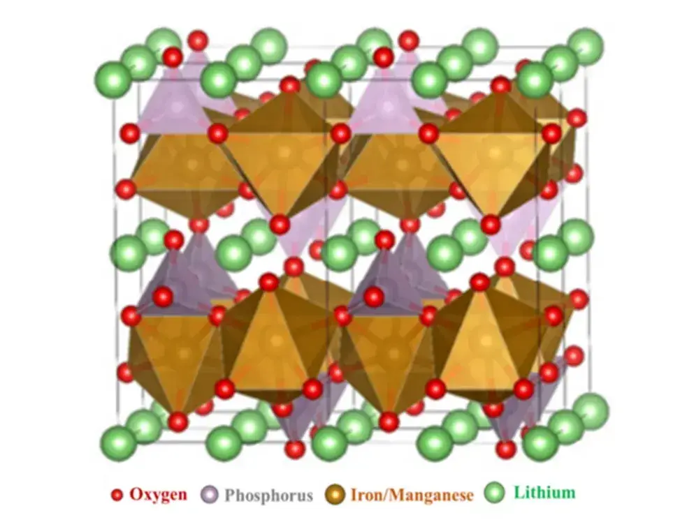
Figure 1. Crystal structure of LMFP (LiMnxFe1-xPO4) — shares the olivine framework of LiFePO₄, with Mn/Fe occupying M2 octahedral sites. Mn substitution raises the electrode potential to ~4.1 V vs. Li⁺/Li versus 3.4 V for LFP, while the stable PO₄ framework maintains structural integrity during cycling[1]
| Property | LFP (LiFePO4) | LMFP (LiMnxFe1−xPO4) |
|---|---|---|
| Crystal structure | Olivine (triphylite) | Olivine (same framework) |
| Voltage platform | ~3.4 V vs. Li⁺/Li | ~4.1 V vs. Li⁺/Li |
| Electronic energy gap | ~0.3 eV (semiconductor) | ~2 eV (insulator) |
| Intrinsic conductivity | ~10−9 S/cm | Much lower (~10−9–10−11 S/cm) |
| Conductivity remedy | Carbon coating | Carbon coating (critical); nanotechnology; ion doping |
| Structural stability | High | High (same PO4 framework) |
The IEST PRCD3100 Powder Resistivity and Compaction Density Measurement System was used to characterize five LMFP cathode materials (LMFP-1 through LMFP-5) for both electronic resistivity and compaction density across a controlled pressure range. Two-probe measurement mode was selected. Test parameters: pressure range 10–200 MPa, increments of 20 MPa, hold time 10 s per step.
The PRCD3100 applies controlled compressive pressure to a powder sample placed between two electrodes, simultaneously recording resistivity, compaction density, and sample thickness in real time at each pressure step — providing the simultaneous conductivity and mechanical data needed for comprehensive LMFP material screening.
 |
 |
Figure 2. IEST PRCD3100 for LMFP characterization: (a) instrument appearance; (b) internal structure — pressure mechanism, two-probe assembly, and displacement sensor for simultaneous powder resistivity and compaction density measurement at 10–200 MPa.
In the early development of lithium manganese iron phosphate, limited by its low conductivity and multiplier performance, the commercialization process is slow.With the progress of modification technologies such as carbon coating, nanotechnology and lithium filling technology, its conductivity has been improved to some extent, and the electrochemical properties of lithium manganese iron phosphate have been improved by controlling particle morphology, nano-chemistry and ion doping.
Material conductivity evaluation can be used as an effective way to evaluate material physicochemical properties. Figure 3 shows the resistivity test results of five different lithium manganese iron phosphate materials. The resistivity results reveal two distinct performance tiers:
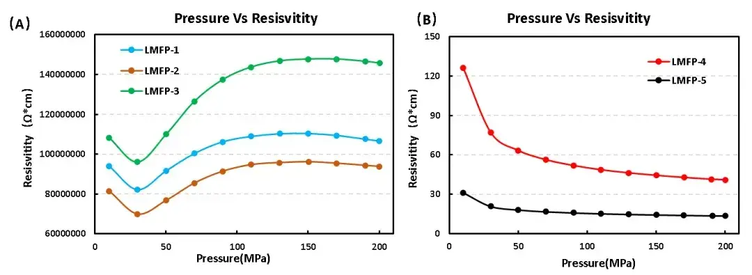
Figure 4. Compaction density vs. pressure for five LMFP materials. LMFP-4 and LMFP-5 achieve higher compaction density than LMFP-1/2/3 — indicating that material modification benefits both electronic conductivity and electrode packing density simultaneously. Better compaction density under identical calendering pressure translates to higher volumetric energy density in the finished electrode.
The material compaction density is closely related to the specific capacity, efficiency, internal resistance and battery cycle performance of lithium-ion battery. To further differentiate LMFP-4 and LMFP-5 — the two best-performing materials in conductivity and compaction — compression and pressure-relief tests were performed to quantify their mechanical properties:
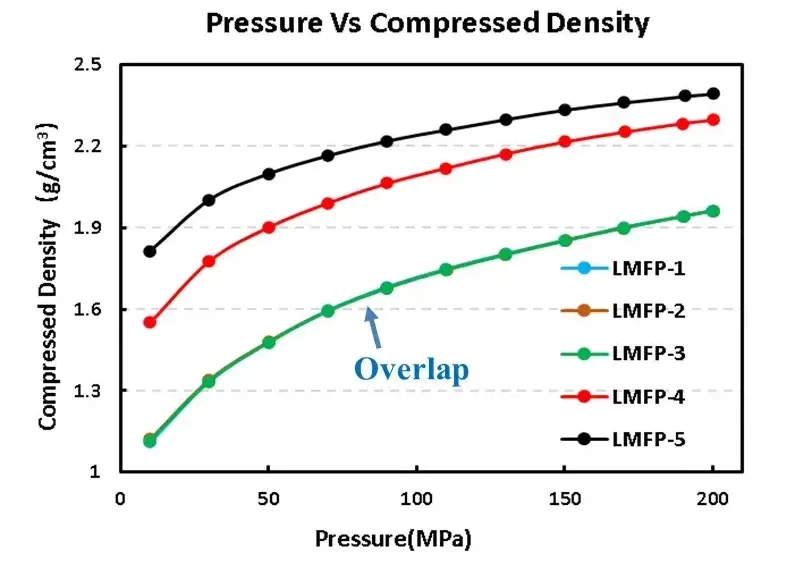
Figure 4. Compaction density test results of the five LMFP materials
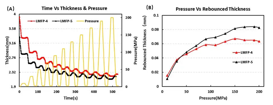
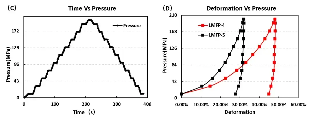
Figure 5. Stress and strain curves during compression and unloading of two LMFP materials
| Name | Reversible Deformation | Irreversible Deformation | Max Deformation |
|---|---|---|---|
| LMFP-4 | 3.24% | 44.90% | 48.14% |
| LMFP-5 | 4.36% | 27.66% | 32.02% |
The compression and rebound results confirm a mechanical property difference between LMFP-4 and LMFP-5 that is invisible in simple conductivity or compaction density measurements:
LMFP (LiMnxFe1-xPO4) is a high-potential olivine cathode material (4.1 V vs. Li⁺/Li) that extends LFP’s voltage platform by 0.7 V while retaining structural stability — but its intrinsically low electronic conductivity (~2 eV energy gap, insulator behavior) requires modification before practical use. This study used the IEST PRCD3100 to characterize powder resistivity and compaction density of five LMFP materials and compression/rebound properties of two:
[1] Tfyac E , Ying L, Zf D, et al. Improving the cycling stability and rate capability of LiMn0.5Fe0.5PO4/C nanorod as cathode materials by LiAlO2 modification. ScienceDirect[J].Journal of Materiomics, 2020, 6(1):33-44.
[2] Ma Guoxuan, Liu Rui, Liu Hongquan, et al. Study on cathode materials coated with lithium manganese iron phosphate [J].Journal of Shandong University of Science and Technology: Natural Science Edition, 2020,39 (6): 7.
[3]Dong D A, Ym A, Mk A, et al. Holey reduced graphene oxide/carbon nanotube/LiMn0.7Fe0.3PO4 composite cathode for high-performance lithium batteries .ScienceDirect [J].Journal of Power Sources, 449.
LMFP shares the same olivine (triphylite) crystal structure as LiFePO4 (LFP): Li+ ions occupy M1 octahedral sites along channels parallel to the b-axis, enabling Li+ insertion and extraction during cycling; Mn/Fe mixed transition-metal ions occupy M2 octahedral sites; and PO4 tetrahedra provide the three-dimensional rigid framework that gives both LFP and LMFP their exceptional structural stability during cycling. The key structural difference from LFP is the partial substitution of Mn for Fe in the M2 sites, which raises the electrode potential from 3.4 V (Fe2+/Fe3+ redox) to approximately 4.1 V vs. Li+/Li (Mn2+/Mn3+ redox) — providing higher energy density while maintaining the stable olivine framework. Both LFP and LMFP have the same space group (Pnmb) and similar lattice parameters.
LMFP has poor intrinsic electronic conductivity because its electron transition energy gap is approximately 2 eV — classifying it as an insulator rather than a semiconductor. This is significantly larger than LFP’s 0.3 eV gap, meaning LMFP has even fewer thermally activated charge carriers and much lower inherent electronic conductivity (estimated at 10-9 to 10-11 S/cm for unmodified LMFP). Three strategies are used to overcome this limitation: (1) carbon coating — a conductive carbon shell around each LMFP particle suppresses particle growth (reducing Li+ diffusion distance), provides an electronic conduction pathway bypassing the resistive LMFP lattice, and significantly improves effective powder resistivity; (2) particle size reduction to nanoscale — shorter solid-state diffusion distances mitigate the kinetic consequences of low conductivity; (3) ion doping — aliovalent cation substitution can introduce additional charge carriers and improve electronic conductivity. Powder resistivity measurement by PRCD3100 directly quantifies the effectiveness of these modification approaches without requiring full electrochemical cell assembly.
LMFP offers a higher voltage platform (~4.1 V vs. 3.4 V for LFP) that increases gravimetric and volumetric energy density by approximately 15–20% for the same cathode mass — without requiring the more expensive or less stable NMC or NCA chemistries. Both materials share the same stable olivine structure, similar cycle life characteristics, and similar safety profiles. The trade-offs: LMFP has significantly poorer intrinsic electronic conductivity than LFP (energy gap 2 eV vs. 0.3 eV), making carbon coating and particle engineering more critical for LMFP than for LFP; LMFP also has Mn-related challenges including Mn dissolution in electrolyte at elevated temperatures (Mn2+ Jahn-Teller distortion) and more complex synthesis requirements. For low-temperature performance, LMFP and LFP show different characteristics because the Mn2+/Mn3+ and Fe2+/Fe3+ redox pairs have different activation barriers at low temperature — a consideration for EV applications in cold climates.
LMFP compaction density is measured by applying controlled compressive pressure (typically 10–200 MPa) to a defined mass of LMFP powder between two electrodes and recording the resulting sample thickness at each pressure step — density = mass / (area × thickness). The IEST PRCD3100 system performs this measurement simultaneously with electronic resistivity, providing both parameters in a single test. Compaction density matters because it directly determines electrode volumetric energy density: higher compaction under the same calendering pressure means more active LMFP material per unit electrode volume, improving cell energy density without changing cell dimensions. Compaction density is also influenced by particle shape, size distribution, and mechanical properties — materials with lower compression modulus (more easily compacted) and lower elastic rebound achieve higher final compaction density at practical calendering pressures. In this study, LMFP-4 achieves higher compaction density than LMFP-5 due to its lower compression modulus and smaller elastic rebound after pressure release.
