-
iestinstrument
Three Stages of Lithium Plating and Dynamic Evolution Processes in Pouch C/LiFePO4 Batteries
First Authors: Ying Lin, Wenxuan Hu
Corresponding Author: Yong Yang
Affiliation: Xiamen University
Equipment Used: IEST Silicon-Based Anode Swelling In-Situ Screening System(RSS1400), IEST In-Situ Cell Swelling Testing System(SEW2100)
1. Research Background
Lithium-ion batteries (LIB) are widely used in the field of new energy due to their excellent energy and power density. However, graphite-based anode materials may experience Li plating under harsh conditions such as fast charging and low temperatures. Uncontrolled lithium plating can lead to the rapid accumulation and growth of “dead lithium” and the solid electrolyte interphase (SEI), and the continuous growth of dendrites may puncture the separator, causing a short circuit between the anode and cathode, which can trigger thermal runaway. Existing studies have proposed various in-situ and ex-situ detection methods to determine when Li plating occurs, but these methods are limited to identifying the onset of Li plating and cannot effectively describe the subsequent evolution of Li plating. In this work, researchers employed a combined analysis method using in-situ dynamic electrochemical impedance spectroscopy (DEIS) and thickness measurements to comprehensively study the evolution process of Li plating, including the occurrence of lithium plating and the changes in lithium deposition states. The results of this study will help to understand the evolution process of graphite Li plating and provide new insights into the operation of lithium-ion batteries under harsh conditions and battery safety management.
2. Work Overview
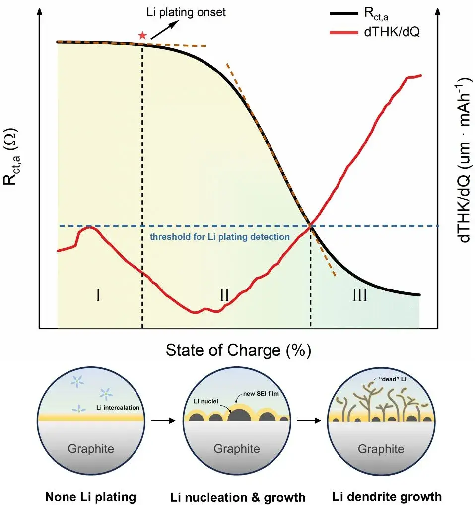
Recently, Professor Yang Yong’s team at Xiamen University comprehensively studied the evolution process of Li plating on graphite surfaces in graphite/LiFePO4 pouch batteries under harsh conditions (low temperature/room temperature fast charging) using a combined analysis method of in-situ dynamic electrochemical impedance spectroscopy (DEIS) and thickness measurements. This work expands the application of impedance spectroscopy and thickness measurement in detecting Li plating. Researchers found that the anode charge transfer resistance Rct,a exhibits a three-stage variation pattern as Li plating progresses. Combined with mass spectrometry titration (MST) and scanning electron microscopy, they confirmed that these three stages correspond to different Li plating evolution processes: non-plating, lithium nucleation & growth, and dendrite growth. The study also extensively analyzed the effects of lithium plating and different lithium deposition states on battery capacity degradation. This research titled “Unveiling the Three Stages of Li Plating and Dynamic Evolution Processes in Pouch C/LiFePO4 Batteries” was published in the prestigious journal《Advanced Energy Materials》.
3. Content Description
In this study, researchers employed a combined analysis method of in-situ dynamic electrochemical impedance spectroscopy (DEIS) and thickness measurements to comprehensively investigate the Li plating evolution process in graphite/LiFePO4 pouch batteries (Figure 1). The DEIS method involves continuously applying AC perturbation signals to the battery during charging to obtain electrochemical impedance spectroscopy (EIS) spectra at different state of charge (SOC) levels. To enhance SOC resolution in obtaining EIS spectra, low-frequency information was disregarded, with perturbation signal frequencies ranging from 50 kHz to 5 Hz and an EIS spectrum obtained approximately every 33 seconds with <1% SOC resolution. Additionally, the researchers quantitatively analyzed the negative electrode charge transfer resistance Rct, a over the charging process using Distribution of Relaxation Times (DRT). Regarding thickness measurements, the researchers first utilized the IEST(RSS)Silicon-Based Anode Swelling In-Situ Screening System. By assembling graphite and LiFePO4 electrode sheets with zero-strain material lithium titanate (LTO) to form full cells, thickness variation curves under a testing accuracy of 0.1 µm were obtained for LTO//LFP and LTO//Gr configurations at different C-rates (Figure 3). Since LTO is a zero-strain material, the observed thickness changes were attributed entirely to LFP and graphite. The researchers concluded from these experiments that the overall cell thickness variation is primarily governed by the graphite negative electrode, while the effect of LiFePO4 positive electrode thickness variation on the overall dT/dQ pattern can be neglected. Importantly, using the (RSS)Silicon-Based Anode Swelling In-Situ Screening System allows for decoupling the variation patterns of any other electrode materials during charge-discharge processes. Furthermore, in the low-temperature lithium plating monitoring experiments, the IEST provided SEW2100 in-situ cell swelling testing system was utilized. The pouch batteries were temperature-controlled (0°C) and subjected to precise constant pressure (285 kg) throughout the experiment. Real-time thickness changes of the batteries were recorded, and based on the significant volume expansion caused by Li plating compared to lithium insertion, the real-time thickness changes were differentiated with respect to capacity (dT/dQ). A Li plating threshold was set, indicating the occurrence of Li plating once dT/dQ exceeded this threshold during the charging process.
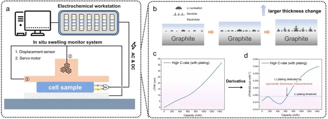
Figure 1. Schematic diagram of the in-situ dynamic electrochemical impedance-thickness measurement device used for Li plating detection experiments (consisting of an electrochemical workstation and an in-situ expansion test system), and a method for detecting the occurrence of Li plating by thickness measurement.
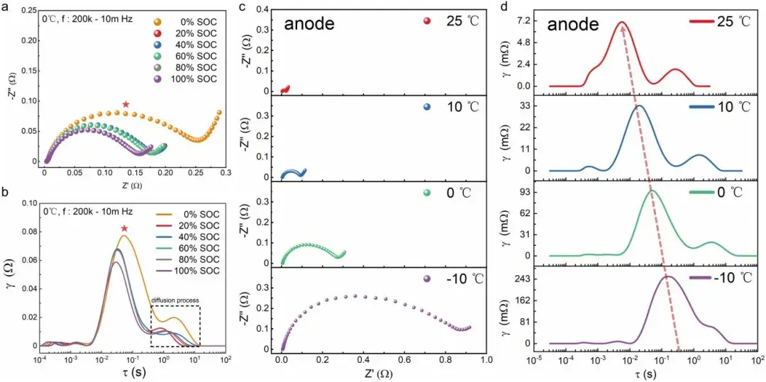
Figure 2. Shows the negative electrode EIS spectra (Nyquist plot and DRT) at different state of charge (SOC) and temperatures.
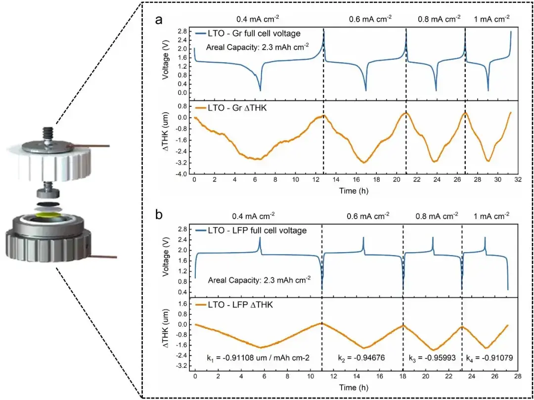
Figure 3. illustrates the decoupling of graphite and LiFePO4 expansion behaviors using LTO.
Through the combined analysis technique of impedance and thickness testing proposed above, researchers can simultaneously analyze impedance and thickness changes during Li plating in pouch cells and compare the precision differences in indicating Li plating between the two methods. At low temperatures (0°C), researchers used different C-rates to charge pouch cells to induce varying degrees of lithium plating (Figure 5). In terms of impedance, under 0.1C charging conditions, Rct,a linearly decreases during the charging process; at 0.2C charging, Rct,a experiences a sudden acceleration after linear decrease, marking the onset of Li plating (Rct,a decreases after Li plating occurs); while at 0.5C charging, Rct,a shows a three-stage variation pattern, with an additional third stage displaying a plateau feature, which is reported for the first time in the literature. Researchers suggest that during Stage II, the reaction at the negative electrode transitions gradually from lithium insertion to Li plating, whereas in Stage III, the reaction at the negative electrode is predominantly driven by lithium plating. Regarding thickness measurements, under 0.1C and 0.2C charging conditions, the thickness/capacity differential curves (dT/dQ) did not exceed the lithium plating threshold, indicating no lithium plating under these charging conditions according to thickness measurements. However, at 0.5C, dT/dQ exceeded the lithium plating threshold after charging approximately 1200 mAh, indicating the detection of lithium plating signals at this SOC through thickness measurements. This demonstrates that the SWE2100 in-situ cell expansion testing system can real-time detect whether lithium plating occurs in the cell, aiding in understanding the complex lithium plating behaviors in pouch batteries. The results indicate that DEIS can indicate the onset of lithium plating earlier than thickness methods. This is because DEIS, as an electrochemical method, is more sensitive to the occurrence of Li plating (charge transfer process), although it cannot provide specific physical information. In contrast, thickness measurement is a macroscopic testing method, less sensitive to Li plating compared to electrochemical methods but can reflect the morphology and severity of lithium plating to some extent. It is noteworthy that the beginning of Stage III in impedance analysis and the SOC indicating lithium plating in thickness measurement are highly consistent, indicating that both methods indicate the same evolution process of lithium plating, which will be discussed in detail in the next chapter.
In conclusion, both impedance and thickness measurements can detect the process of lithium plating, but they provide different types of information and potential physical significance. They complement each other and cross-validate findings. Electrochemical information (Rct,a) and structural information (dT/dQ) together form multidimensional descriptors to accurately determine the state of lithium deposition, facilitating a more comprehensive understanding of the evolution process of lithium plating.
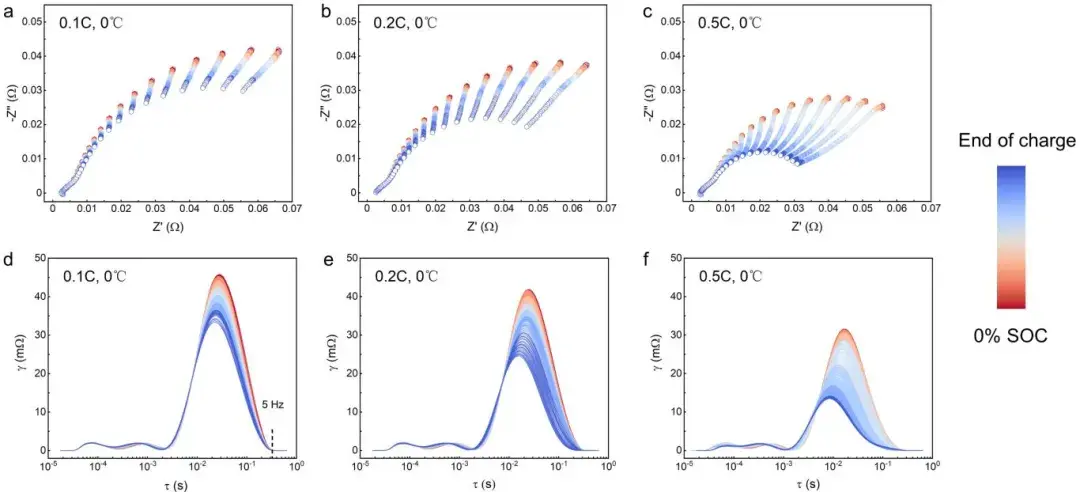
Figure 4. Changes in EIS spectra (Nyquist plot and DRT) of soft-pack batteries during charging at different rates.
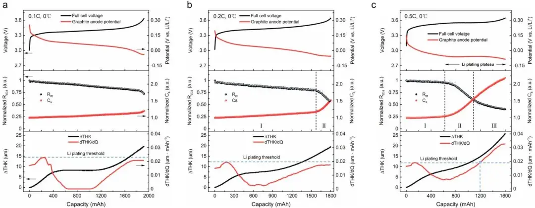
Figure 5. Shows the characteristics of thickness and impedance changes during lithium plating in pouch cells. From top to bottom, it includes the cell voltage curve, negative electrode charge transfer impedance/capacity changes, and thickness variation.
The researchers first validated the accuracy of Rct,a in indicating the onset of lithium plating through Incremental Capacity Analysis (ICA) and differential Open Circuit Voltage (dOCV) analysis (Figure 6). Subsequently, battery cells at three different stages of Rct,a variation were dismantled and characterized under low temperature (0°C/0.4C) and high-rate room temperature (25°C/3C) charging conditions using Mass Spectrometry Titration (MST) and Scanning Electron Microscopy (SEM). MST and SEM analyses collectively confirmed that Stage I involves graphite lithiation, Stage II comprises lithium nucleation and growth, and Stage III exhibits extensive dendrite growth (Figure 7). This conclusion holds true under different temperatures and charging rates, demonstrating that the combined analysis technique of impedance and thickness testing contributes to a comprehensive understanding of the evolution process of lithium plating.
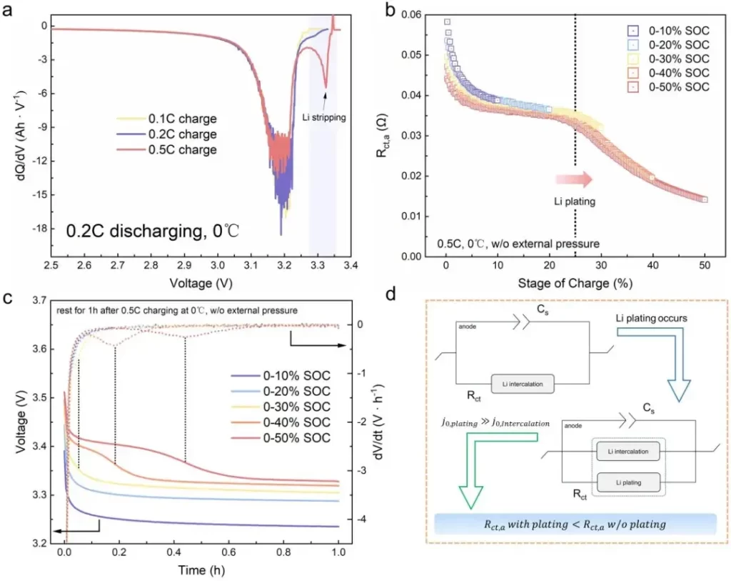
Figure 6. Incremental Capacity Analysis (ICA) and Open Circuit Voltage Relaxation (dOCV) analysis to validate the accuracy of DEIS method in indicating lithium plating.
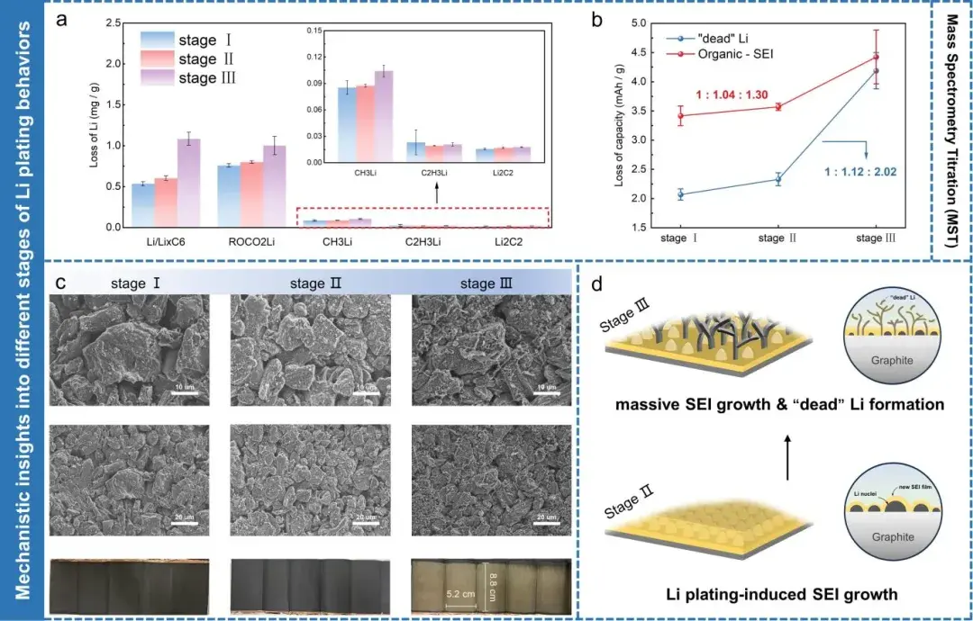
Figure 7. (a) Mass spectrometry titration results of graphite electrode sheets charged to three different stages of Rct,a variation. (b) Capacity loss attributed to “dead lithium” and different organic SEI components. (c) Scanning electron microscopy and optical images of three representative cells at different stages of Rct,a variation. (d) Schematic illustration of lithium plating behavior on graphite surface during Stages II/III of Rct,a variation.
Furthermore, researchers tested and obtained the variation patterns of Rct,a at different charging rates under 0°C conditions. They plotted boundaries for lithiation and lithium plating occurrence based on the inflection points of Rct,a under different charging rates, delineating three regions corresponding to three distinct stages of lithium plating (Figure 8). By conducting relevant experiments to generate similar charts, researchers can accurately mitigate the occurrence of lithium plating or extensive dendrite growth during battery cycling.
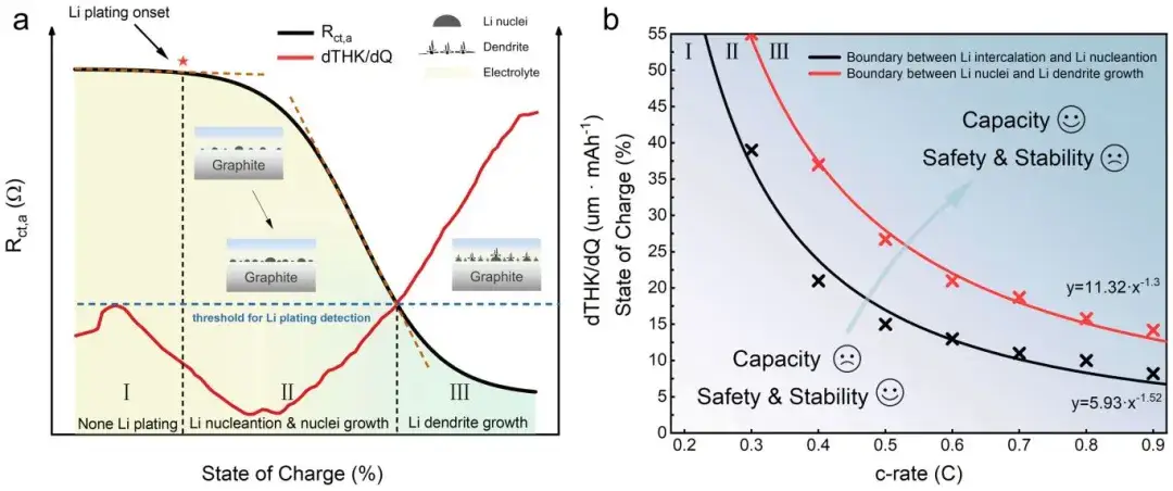
Figure 8. Schematic of in-situ impedance-thickness measurement method monitoring the lithium plating process, along with boundaries indicating different stages of lithium plating occurrence.
During continuous charging cycles, researchers observed that Stage II (lithium nucleation and growth) and Stage III (extensive dendrite growth) in the second cycle occurred earlier compared to the first cycle. They attributed this to residual lithium on the graphite surface from the first discharge cycle, which reduced the nucleation barrier for subsequent Li plating during charging, thereby leading to premature lithium plating. Additionally, researchers cycled three batteries within different SOC ranges corresponding to the proposed stages of Li plating evolution (no plating, lithium nucleation and growth, dendrite growth). They utilized an internally developed Electromotive Force (EMF) measurement method to analyze the State of Health (SOH) and Active Lithium Loss (LLI) of batteries across different cycle numbers. The results indicated that early onset of Li plating and dendrite growth accelerated battery capacity loss, potentially causing capacity drops. This underscores the critical importance of detailed analysis and monitoring of Li plating evolution processes to advance the application of lithium-ion batteries under extreme conditions.
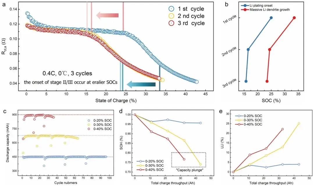
Figure 9. (a) Variation of Rct,a across three cycles, and (b) starting SOC of Stage II/Stage III during these cycles. (c) Discharge capacity variation with cycle number for three batteries cycled within different SOC ranges. Under equivalent total charge throughput, changes in (d) State of Health (SOH) and (e) Active Lithium Loss (LLI) of batteries.
4. Conclusion
This study employs a combined analysis technique of in-situ impedance and thickness measurements to investigate the evolution of Li plating from both electrochemical and thickness change perspectives. By avoiding the limitations of single-method studies, it underscores the significance of approaching problems from multiple angles. While both impedance and thickness measurements detect Li plating processes, they offer different information and underlying physical implications, complementing each other. When Rct,a serves as an indicator of Li plating, it exhibits a three-stage pattern: a slow linear decrease (Stage I), accelerated decline (Stage II), and a plateau (Stage III). These stages correspond to lithium insertion, a mixed region transitioning from lithium intercalation to plating dominance, and nearly complete Li plating reaction, respectively. The first inflection point signifies the onset of lithium plating, while the second indicates lithium dominance in interfacial reactions. On the other hand, using dT/dQ as a lithium plating indicator captures the moment when lithium nucleation transitions to extensive dendrite growth, but it overlooks nucleation and growth stages, closely aligning with the onset of Stage III in Rct,a variation.
Through dismantling and characterization analysis, researchers confirmed that the three stages of negative electrode charge transfer impedance (Rct,a) correspond to three distinct Li plating evolution processes: no plating, nucleation & growth of lithium nuclei, and dendrite growth. Furthermore, the aging status of batteries cycled at different State of Charge (SOC) levels indicated that lithium dendrite growth and significant SEI formation led to considerable capacity loss compared to scenarios without plating or dendrite growth. Additionally, without precise monitoring of lithium deposition states, lithium plating can become uncontrollable, potentially causing rapid capacity degradation or even capacity “drop.” This work focuses on analyzing the various evolution processes of lithium plating in commercial pouch cells, providing novel insights into the complex phenomenon of Li plating. It contributes to the development of Battery Management Systems (BMS) and potential applications involving “graphite-lithium” hybrid negative electrodes.
5. Original Article
Ying Lin, Wenxuan Hu, Meifang Ding, Yonggang Hu, Yufan Peng, Jinding Liang, Yimin Wei, Ang Fu, Jianrong Lin, Yong Yang. Unveiling the Three Stages of Li Plating and Dynamic Evolution Processes in Pouch C/LiFePO4 Batteries. Advanced Energy Materials. 2024, 2400894.
Subscribe Us
Contact Us
If you are interested in our products and want to know more details, please leave a message here, we will reply you as soon as we can.


