
24 Battery Charge-Discharge Test Steps: Complete Parameter Reference Guide

Updated on 2026/06/18
Table of Contents

Abstract

A charge-discharge test on battery cycler equipment is built from individual test steps, each defining a fixed control mode (constant current, constant voltage, constant power, etc.), a primary control parameter, and a transition condition that ends the step. This guide catalogs 24 core charge-discharge steps—from basic CC/CV charge and discharge through advanced characterization techniques like EIS, GITT, and pulse testing—covering each step’s purpose, primary parameters, transition conditions, and typical applications. For example, a standard CC-CV charge step (the most common lithium-ion charging protocol) uses a constant current phase (e.g., 1C) until reaching a target voltage (e.g., 4.2V), then holds that voltage while current decays to a cutoff threshold—typically 0.05C. All 24 steps are developed by the IEST Instrument R&D team for modular, no-code test protocol design on the IEST high-precision battery cycler platform.

1. Background

In battery R&D and quality control, charge-discharge test equipment serves as a diagnostic center for cells. By precisely controlling parameters such as current, voltage, and temperature, it not only measures fundamental metrics like capacity and efficiency but also enables deep analysis of material properties, aging mechanisms, and safety risks. However, faced with complex testing requirements, how do you select the appropriate step combination? How do you capture the key data you need through parameter configuration?

This article systematically outlines 24 core charge-discharge steps, spanning from basic constant-current operations to advanced pulse and EIS testing, enabling you to:

  • Rapidly match test scenarios (formation, lifecycle, fast-charge, low-temperature performance)
  • Precisely interpret parameter logic (primary parameters, transition conditions, data recording)
  • Avoid common testing pitfalls (overcharge protection, temperature compensation, polarization mitigation)

All steps are developed by the IEST Instrument R&D team. Modular step editing requires no programming expertise for rapid test protocol deployment. Contact us for details on the IEST high-precision battery cycler test system family.
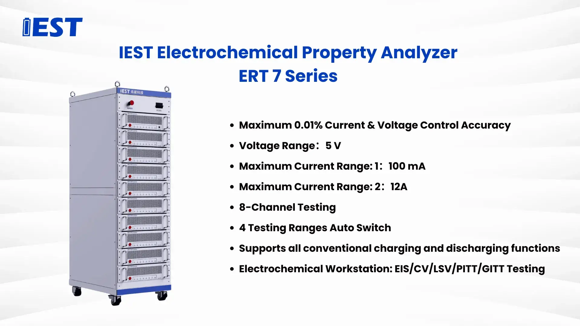
lEST Electrochemical Property Analyzer ERT-7 Series battery cycler

Figure 2. IEST Electrochemical Property Analyzer (ERT 7 Series) — battery cycler platform supporting all 24 charge-discharge test steps described below

2. Quick Reference: All 24 Charge-Discharge Steps at a Glance

Table 1. Battery testing steps, primary parameters, and typical uses
# Step Primary Parameter Typical Use
2.1 Rest Time / voltage / temperature threshold Polarization recovery, pre-test stabilization
2.2 CC Charge Charge current (C-rate) Fast charging, formation, capacity calibration
2.3 CC Discharge Discharge current Discharge performance at varied C-rates
2.4 CV Charge Charge voltage Saturation charging, overcharge prevention
2.5 CV Discharge Discharge voltage Regulated power output simulation
2.6 CC-CV Charge CC current + CV voltage Standard Li-ion charging protocol
2.7 CC-CV Discharge CC current + CV voltage Precise available capacity measurement
2.8 Cycle Cycle count Lifecycle testing, aging modeling
2.9 Conditional Jump Trigger threshold Adaptive protocols, emergency response
2.10 Pause Trigger condition Mid-test inspection, segmented testing
2.11 CP Charge Charge power (W) Fast-charge protocol validation (PD/QC)
2.12 CP Discharge Discharge power (W) Dynamic load simulation, peak power testing
2.13 CR Charge Resistance value (Ω) Educational demos, low-efficiency charging
2.14 CR Discharge Resistance value (Ω) Basic discharge characterization (lead-acid)
2.15 Thermal Chamber Sync Target temp + ramp rate Temperature-dependent validation, BMS testing
2.16 EIS Frequency range, amplitude SEI/CEI analysis, charge-transfer resistance
2.17 CV (Cyclic Voltammetry) Scan rate, voltage range Redox reversibility, kinetics
2.18 LSV Scan rate, start/end voltage Reaction onset, diffusion limits
2.19 CA Voltage hold, duration Capacitive behavior analysis
2.20 CP (Chronopotentiometry) Current hold, duration Li plating/stripping overpotential
2.21 GITT Pulse current/duration, relaxation Li+ diffusion coefficient
2.22 PITT Voltage step, relaxation cutoff Phase-transition thermodynamics
2.23 Leakage Current Test Rest duration, hold voltage Charge retention / self-discharge
2.24 Pulse Step Pulse amplitude, duration, count HPPC resistance estimation, dynamic response

3. Step Catalog: Full Parameter Detail for Each of the 24 Charge-Discharge Steps

3.1 Rest
Purpose: Suspends charge/discharge to stabilize cell state or await an external trigger.
Transition Conditions: Time termination (default). Optional: voltage threshold (e.g., post-rest fluctuation ≤0.01 V), temperature threshold (requires auxiliary module).
Data Recorded: Voltage, temperature, auxiliary parameters (e.g., pressure) at fixed intervals.
Applications: Inter-cycle polarization recovery; pre-test stabilization.
3.2 Constant-Current (CC) Charge
Purpose: Charges at fixed current until voltage, time, or temperature limits are reached.
Primary Parameter: Charge current (absolute value or C-rate).
Transition Conditions: Voltage limit (e.g., 4.2 V), time limit, temperature limit (e.g., ≥45 °C).
Applications: Fast charging, formation, polarization studies, capacity calibration.
3.3 Constant-Current (CC) Discharge
Purpose: Discharges at fixed current until voltage, capacity, or time limits are reached.
Primary Parameter: Discharge current (e.g., 0.5C).
Transition Conditions: Voltage limit (e.g., 2.8 V), capacity limit (e.g., 80% nominal capacity), time limit.
Applications: Discharge performance evaluation at varied C-rates.
3.4 Constant-Voltage (CV) Charge
Purpose: Charges at fixed voltage; current decays naturally to a cutoff.
Primary Parameter: Charge voltage (e.g., 4.2 V).
Transition Conditions: Current cutoff (e.g., 0.05C), time limit.
Applications: Saturation charging; overcharge prevention. Note: An initial CC phase typically transitions to CV upon reaching the target voltage — see the CC-CV charge step below.
3.5 Constant-Voltage (CV) Discharge
Purpose: Discharges at fixed voltage; current adjusts dynamically with load.
Primary Parameter: Discharge voltage (e.g., 3.0 V).
Transition Conditions: Current limit (e.g., ≤0.05C), time limit.
Applications: Simulating regulated power output; load-response testing.
3.6 CC-CV Charge
Purpose: Constant-current charge followed automatically by constant-voltage charge, holding until current cutoff.
Primary Parameters: CC current (e.g., 1C), CV voltage (e.g., 4.2 V).
Transition Conditions: CV time limit, CV current cutoff (commonly 0.05C for lithium-ion cells).
Applications: Standard lithium-ion charging protocol (e.g., consumer electronics). This is the most widely used charge protocol and the basis for most formation and capacity‑calibration test plans.
3.7 CC-CV Discharge
Purpose: Constant-current discharge followed by constant-voltage discharge, holding until current cutoff.
Primary Parameters: CC current (e.g., 0.5C), CV voltage (e.g., 2.8 V).
Transition Conditions: CV time limit, CV current cutoff.
Applications: Precise available-capacity measurement.
3.8 Cycle
Purpose: Executes a user‑defined charge-discharge sub‑step sequence repeatedly.
Primary Parameter: Cycle count (e.g., 100).
Sub‑step Configuration Example: [CC‑CV Charge → Rest → CC Discharge].
Transition Conditions: Capacity fade threshold (e.g., ≤80% of initial capacity), temperature limit (e.g., ≥50 °C).
Applications: Lifecycle/cycle‑life testing; aging modeling.
3.9 Conditional Jump
Purpose: Branches to a specified step based on real‑time test conditions (IF–THEN logic).
Primary Parameter: Trigger threshold (voltage, current, temperature, or capacity).
Target Step: A designated step number in the test plan.
Applications: Adaptive testing protocols; automated emergency response (e.g., abort on over‑temperature).
3.10 Pause
Purpose: Halts the test until the user manually resumes it.
Trigger Conditions: e.g., after every 5 cycles.
Applications: Mid‑test inspections; segmented long‑term testing schedules.
3.11 Constant-Power (CP) Charge
Purpose: Charges at fixed power; voltage and current adjust dynamically to maintain constant power output.
Primary Parameter: Charge power (e.g., 10 W).
Transition Conditions: Voltage limit, time limit.
Applications: Fast‑charge protocol validation (e.g., USB PD/QC standards); thermal profiling under realistic charger behavior.
3.12 Constant-Power (CP) Discharge
Purpose: Discharges at fixed power; voltage and current adjust dynamically.
Primary Parameter: Discharge power (e.g., 20 W).
Transition Conditions: Voltage limit, time limit.
Applications: Dynamic load simulation (e.g., power tools); peak power capability testing.
3.13 Constant-Resistance (CR) Charge
Purpose: Charges through a fixed resistor; current decays naturally as voltage rises.
Primary Parameter: Resistance value (e.g., 10 Ω).
Applications: Educational demonstrations; low‑efficiency charging scenarios.
3.14 Constant-Resistance (CR) Discharge
Purpose: Discharges through a fixed resistor; current decays naturally as voltage drops.
Primary Parameter: Resistance value (e.g., 5 Ω).
Applications: Basic discharge characterization (e.g., lead‑acid batteries); cost‑effective discharge testing.
3.15 Thermal Chamber Synchronization
Purpose: Controls an external thermal chamber for precise environmental conditioning during the test.
Primary Parameter: Target temperature (e.g., −40 °C to 85 °C), ramp rate (e.g., 5 °C/min).
Applications: Temperature‑dependent performance validation; BMS thermal‑protection logic testing. Note: currently compatible only with IEST chambers; custom protocol development available on request.
3.16 EIS (Electrochemical Impedance Spectroscopy)
Purpose: Applies an AC perturbation (0.01 Hz–100 kHz) to measure the cell’s impedance response across frequency.
Primary Parameter: Frequency range, mode (potentiostatic / galvanostatic / dynamic), perturbation amplitude (e.g., 10 mV or 50 mA).
Output Data: Nyquist plots, Bode plots.
Applications: SEI/CEI analysis; charge‑transfer resistance quantification. Precautions: avoid electromagnetic interference; use 4‑wire (Kelvin) measurement at high frequency to eliminate lead resistance error.
3.17 CV (Cyclic Voltammetry)
Purpose: Applies a linear voltage sweep to study redox reaction reversibility and kinetics.
Primary Parameter: Scan rate (e.g., 10 mV/s), voltage range (e.g., 2.5 V–4.2 V).
Output Data: Current‑voltage (I‑V) curves, oxidation and reduction peaks.
Applications: Electrode reversibility assessment; catalyst surface area calculation.
3.18 LSV (Linear Sweep Voltammetry)
Purpose: Applies a single‑direction voltage sweep to analyze reaction onset potential and diffusion limits.
Primary Parameter: Scan rate, start/end voltage.
Applications: Kinetic parameter extraction (e.g., exchange current density); corrosion studies.
3.19 CA (Chronoamperometry)
Purpose: Measures current decay over time at a fixed applied voltage.
Primary Parameter: Voltage hold level, duration.
Applications: Capacitive behavior analysis; voltage‑polarization stability assessment.
3.20 CP (Chronopotentiometry)
Purpose: Tracks voltage evolution over time at a fixed applied current.
Primary Parameter: Current hold level, duration.
Applications: Lithium plating/stripping overpotential studies; phase‑transition analysis.
3.21 GITT (Galvanostatic Intermittent Titration Technique)
Purpose: Alternates short current pulses with relaxation periods to compute the lithium‑ion diffusion coefficient.
Primary Parameter: Pulse current and duration, relaxation time.
Output Data: Voltage relaxation profiles, diffusion coefficient (D).
Applications: Cathode diffusion kinetics characterization; full‑cell transport bottleneck analysis.
3.22 PITT (Potentiostatic Intermittent Titration Technique)
Purpose: Alternates small voltage steps with relaxation periods to measure thermodynamic and transport properties.
Primary Parameter: Voltage step size, relaxation current cutoff.
Applications: Phase‑transition thermodynamics; solid electrolyte interface characterization.
3.23 Leakage Current Test
Purpose: Quantifies self‑discharge rate under a sustained voltage hold.
Primary Parameter: Rest duration (for stabilization), hold voltage.
Applications: Charge retention assessment.
Precautions: requires strict temperature and humidity control, since both directly affect measured leakage current.
3.24 Pulse Step
Purpose: Applies intermittent current pulses to simulate dynamic real‑world loads.
Primary Parameter: Pulse amplitude (charge/discharge), duration, cycle count.
Applications: HPPC‑based internal resistance estimation; dynamic response validation; real‑world usage simulation (EVs, wearables, power tools). Precautions: pulse amplitude must not exceed the cell’s rated current specification.

4. FAQs

4.1 What is the typical CC-CV cutoff current for lithium-ion battery charging?

The typical CC-CV charging cutoff current for lithium-ion batteries is 0.05C, meaning the constant-voltage phase ends once charge current decays to 5% of the cell’s rated capacity (in amp-hours). For example, a 2,000 mAh cell would use a cutoff of approximately 100 mA. Some manufacturers specify a tighter cutoff (0.02C–0.03C) for higher-precision capacity calibration, or a looser cutoff (0.1C) for faster production-line formation where slightly reduced full-charge capacity is an acceptable trade-off for throughput. The CC-CV charge step (Section 2.6) is the standard protocol implementing this behavior: a constant-current phase charges the cell to a target voltage (commonly 4.2 V for standard Li-ion chemistries), then the constant-voltage phase holds that voltage while current decays naturally to the specified cutoff.

4.2 How many stages does CC-CV charging typically have?

Standard CC-CV charging has two stages: a constant-current (CC) stage followed by a constant-voltage (CV) stage. In the CC stage, the charger delivers a fixed current (e.g., 1C) until the cell reaches its target charge voltage. The protocol then automatically transitions to the CV stage, holding that voltage constant while current naturally decays as the cell approaches full charge, until reaching a cutoff current (commonly 0.05C). Some fast-charging protocols use a multi-stage CC-CC-CV approach (multiple step-down constant-current stages before the final CV hold) to balance charge speed against heat generation and lithium-plating risk, but the fundamental two-stage CC-CV structure remains the basis for standard lithium-ion charging.

4.3 What charge-discharge test steps are needed for galvanostatic cycling to evaluate battery capacity, efficiency, and cycle life?

Galvanostatic (constant-current) charge-discharge testing for capacity, efficiency, and cycle life evaluation typically combines three core steps from this 24-step catalog: a CC (or CC-CV) charge step, a rest step for polarization recovery, and a CC discharge step, wrapped inside a Cycle step that repeats this sequence for a defined number of cycles (e.g., 100–1,000+). Coulombic efficiency is calculated each cycle as discharge capacity divided by charge capacity. Cycle life testing typically sets the Cycle step’s transition condition to a capacity-fade threshold (e.g., terminate when discharge capacity falls below 80% of the initial value), which directly defines the cell’s measured cycle life under the tested conditions.

4.4 What is the difference between EIS, GITT, and PITT testing in battery characterization?

EIS, GITT, and PITT are three distinct electrochemical characterization steps that probe different aspects of battery behavior. EIS (electrochemical impedance spectroscopy) applies a small AC perturbation across a frequency range (typically 0.01 Hz–100 kHz) to separate impedance contributions—such as ohmic resistance, charge-transfer resistance, and diffusion impedance—based on their characteristic frequency response, producing Nyquist and Bode plots. GITT (galvanostatic intermittent titration technique) applies short DC current pulses followed by relaxation periods to calculate the lithium-ion diffusion coefficient at each state of charge. PITT (potentiostatic intermittent titration technique) instead applies small voltage steps followed by relaxation, used primarily to study phase-transition thermodynamics and solid-electrolyte-interface behavior. EIS is generally faster and used for interfacial/SEI analysis, while GITT and PITT provide more detailed state-of-charge-resolved transport and thermodynamic data at the cost of longer test time.

4.5 What is a pulse step (HPPC) used for in battery testing?

A pulse step applies short, intermittent current pulses (charge and/or discharge) to a cell to measure its dynamic resistance and voltage response— most commonly implemented as a Hybrid Pulse Power Characterization (HPPC) test. By applying defined-amplitude current pulses at various states of charge and measuring the instantaneous voltage drop, HPPC testing extracts internal resistance (DC-IR) as a function of state of charge, which is essential data for battery management system (BMS) power-limit calculations in electric vehicles. Pulse testing also validates a cell’s response to real-world dynamic loads—such as acceleration events in EVs or burst current draws in power tools and wearables—making it a critical step for application-realistic battery qualification beyond standard constant-current cycling.

Contact Us

If you are interested in our products and want to know more details, please leave a message here, we will reply you as soon as we can.

Contact Us

Please fill out the form below and we will contact you asap!

IEST Wechat QR code