-
iestinstrument

Abstract
Silicon anodes for all-solid-state batteries must accommodate large volume changes while maintaining stable solid-solid contact and rapid Li-ion transport. Conventional encapsulation can preserve particle integrity but impede interparticle ion transport, whereas uncontrolled electrochemical sintering can restore contact but also produce large agglomerates that fracture the electrode.
This study proposed a stress-lensed electrochemical sintering (SLES) strategy in which amorphous Si is conformally deposited at the high-curvature pore entrances of a porous carbon host. During lithiation, these constrictions concentrate expansion-induced stress at interparticle contacts, locally promote atomic diffusion, and direct selective sintering. The resulting Si network remains interconnected while internal pores provide space for volume expansion.
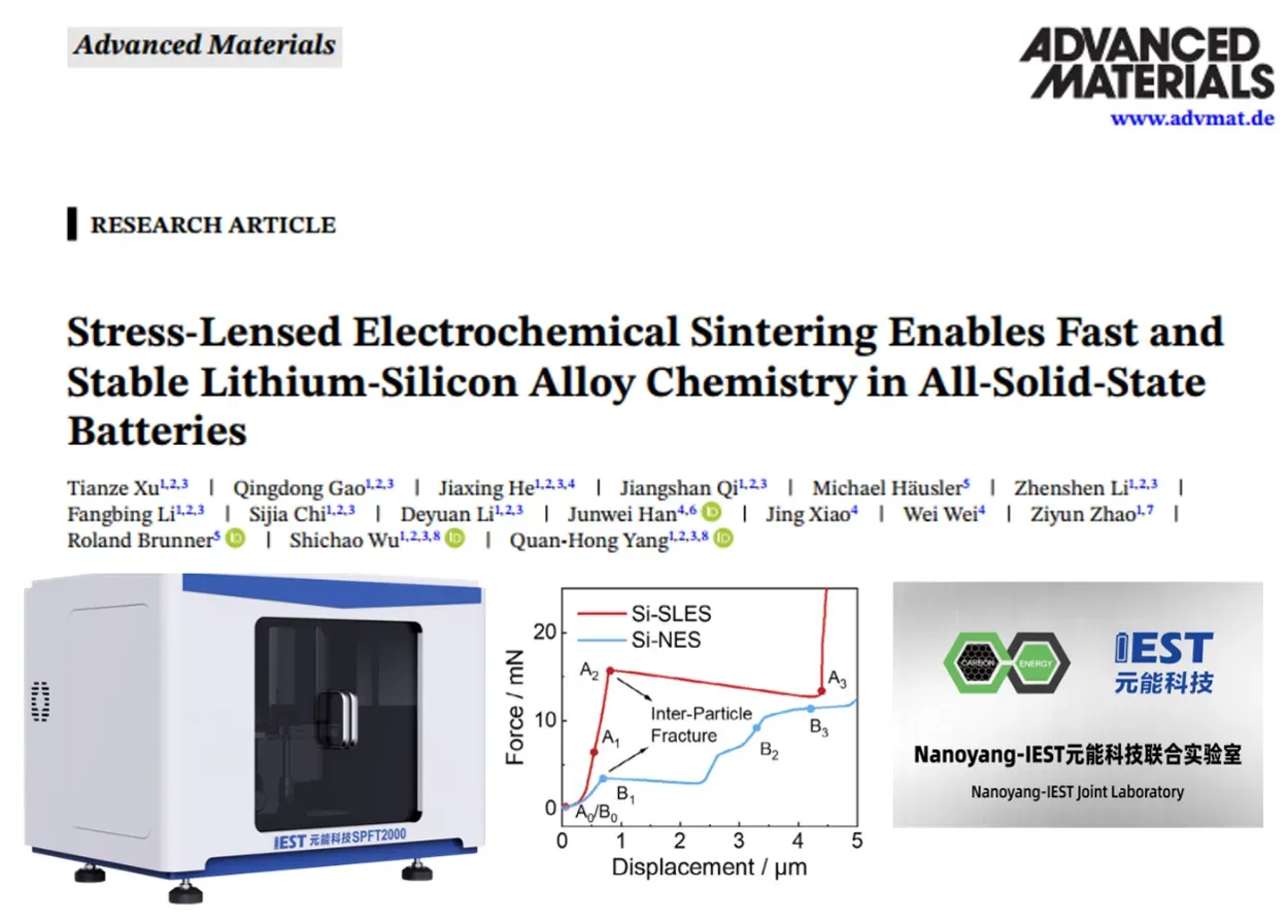
The Si-SLES anode retained approximately 100% of its capacity after 100 cycles and maintains over 60% capacity after 700 cycles in NCM532-based full cells. Single-particle stiffness testing with the IEST SPFT2000 Single-Particle Mechanical Testing System showed a crushing force of 15.7 mN for SLES agglomerates, compared with 3.4 mN for the non-electrochemical-sintering control. These results connect the SLES interfacial structure with improved particle-level mechanical integrity and Li-ion transport.
📄 Source Paper
Tianze Xu1,2,3, Qingdong Gao1,2,3, Quan-Hong Yang1,2,3,8*, Shichao Wu1,2,3,8*, Ziyun Zhao1,7* et al.
DOI: doi.org/10.1002/adma.74090
| Journal: Advanced Materials
| Institutions: Nanoyang Group, Tianjin University of Advanced Carbon and Energy Materials Laboratory, Tsinghua University
✓ IEST SPFT2000 Single Particle Mechanical Properties Test System used in this research
1. The Silicon Anode Challenge in All-Solid-State Batteries
All-solid-state batteries (ASSBs) can improve safety and energy density, but their performance depends on maintaining stable solid-solid interfaces. Silicon is an attractive anode material because its theoretical specific capacity is approximately 3,579 mAh g⁻¹, nearly ten times that of graphite. However, its volume can expand by more than 300% during lithiation and LiₓSi alloy formation, placing severe mechanical strain on the electrode structure.
Electrochemical sintering refers to the stress-driven fusion of adjacent active-material particles during cycling. In silicon anodes, repeated lithiation and delithiation can drive atomic rearrangement at particle contacts and form sintered necks. Controlled sintering may restore ionic contact, whereas uncontrolled sintering produces large agglomerates and nonuniform stress.
This volume change manifests in three interconnected degradation modes: (1) particle pulverization — repeated alloying/de-alloying generates internal stress that fractures individual Si particles; (2) solid–solid interface disconnection — the expanding and contracting Si network loses physical contact with the solid electrolyte, creating dead zones where ion transport is blocked; and (3) electrode-level structural collapse — cumulative particle rearrangement and fracture lead to macroscopic electrode cracking and loss of percolation. These problems are fundamentally exacerbated by an intrinsic electrochemical process: during cycling, neighboring Si particles undergo electrochemical sintering, gradually fusing together. While controlled sintering could theoretically restore ionic connectivity, uncontrolled sintering produces oversized agglomerates that magnify stress concentrations and accelerate electrode fracture.
2. Limitations of Static Constraints
Conventional approaches to accommodating Si volume expansion rely on static constraints, such as carbon coatings and rigid physical isolation. Although these shells can limit outward expansion, they might isolate neighboring Si domains and impede interparticle Li-ion transport. Thin coatings may delay particle contact, but coating fracture can expose Si and allow uncontrolled sintering, agglomeration, and electrode cracking.
These limitations reflect a deeper design principle: static electrode architectures are fundamentally mismatched to the dynamic behavior of high-volume-change alloy anodes. What is needed is a mechanism that guides — rather than suppresses — the dynamic evolution of the silicon structure during cycling.
3. Stress-Lens Electrochemical Sintering Strategy
Stress-Lens Electrochemical Sintering (SLES) — A geometry-guided strategy in which amorphous silicon is conformally deposited at the high-curvature pore entrances of a porous carbon host. During lithiation, these constricted pore openings act as “stress lenses” that concentrate volumetric expansion stress precisely at interparticle contact points, lowering the atomic diffusion barrier and inducing selective, local electrochemical sintering to form a continuous, percolating Si network while preserving internal voids for volume buffering.
Professor Yang Quanhong’s team at Tianjin University, in collaboration with Dr. Zhao Ziyun at Tsinghua Shenzhen International Graduate School and co-authors, developed a stress-lensed electrochemical sintering (SLES) strategy to control where electrochemical sintering occurs. Amorphous Si is conformally deposited at the high-curvature pore entrances of a porous carbon host. During lithiation, these geometric constrictions act as stress lenses that concentrate expansion-induced stress at interparticle contacts.
This focused mechanical energy locally reduces the atomic diffusion barrier for Si rearrangement, promoting the formation of robust, selective sintered connections between adjacent Si domains while maintaining internal porosity to accommodate future volume changes. The outcome is a self-organized, percolating Si network that is simultaneously mechanically robust and ionically conductive — a feature that static encapsulation strategies cannot achieve.
4. Comparison of Silicon-Anode Design Strategies

Figure 1. Comparison of four design paradigms for Si anodes in ASSBs: SLES, non-electrochemical sintering, carbon-coating-delayed sintering, and uncontrolled sintering of uncoated Si.
Figure 1 compares four approaches to controlling Si-particle reconstruction. SLES directs sintering to the pore entrances and forms an interconnected Si network while retaining internal voids. A complete carbon coating suppresses particle contact but impedes interparticle Li-ion transport. A thinner coating delays contact, although cracking can eventually expose Si and permit uncontrolled agglomeration. Without confinement, Si undergoes extensive sintering and loses stable transport pathways. This comparison illustrates how SLES combines controlled interparticle bonding with space for volume expansion.
| Quadrant | Mechanical Constraint | Sintering Control | Resulting Outcome |
|---|---|---|---|
| I — SLES (this work) | Dynamic, stress-guided | Selective electrochemical sintering directed by pore-opening geometry | Continuous percolating Si network; simultaneous mechanical stability and fast Li+ conduction |
| II — Non-electrochemical sintering | Static (full carbon coating) | Sintering suppressed via physical isolation | Poor interparticle ionic conduction; uneven stress distribution |
| III — Carbon-coating delayed sintering | Static (thin carbon shell) | Sintering temporarily delayed | Shell cracks after cycling; particle agglomeration blocks ion-transport pathways |
| IV — Uncontrolled pure-Si sintering | None | Uncontrolled sintering | Severe agglomeration, electrode fracture, and collapse of the long-range conductive network |
5. Synthesis and Multi-Scale Structural Characterization
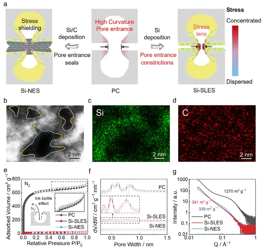
Figure 2. The stress-lens geometry structure design and realization. (a) Synthesis schematic of Si-SLES and Si-NES from PC. (b) Spherical aberration-corrected HAADF-STEM of Si-NES samples, with high-curvature pore entrances highlighted. (c,d) Corresponding (c) Si and (d) C EDS elemental mappings of (b). (e) N₂ adsorption-desorption isotherms, (f) pore size distributions, (g) small-angle X-ray scattering patterns of PC, Si-SLES, and Si-NES samples.
The SLES composite uses a porous carbon host containing ink-bottle-shaped pores with narrow entrances and wider internal cavities. Chemical vapor deposition concentrates amorphous Si near the pore entrances. The Si-NES control has an additional continuous carbon coating that separates adjacent Si domains.
Nitrogen adsorption analysis showed that the Si-SLES retained open micropores after Si deposition, whereas the additional coating in Si-NES closed most of the micropore entrances. The accessible internal pores in SLES provide space for Si volume expansion and help limit the stress accumulation associated with uncontrolled agglomeration and electrode fracture.
6. Stress-Lens Effect and Selective Electrochemical Sintering
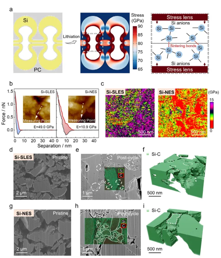
Figure 3. Stress-lens effect and selective electrochemical sintering behavior. (a) Stress distribution at the lithiation state of Si-SLES and the schematic of the role of the stress-lens structure in electrochemical sintering. (b) Force-distance curves from AFM tests on the interparticle gaps of Si-SLES and Si-NES after 1 cycle. (c) AFM modulus mappings of the Si-SLES anode and the Si-NES anode after 1 cycle. (d,g) FESEM cross-sectional images of (d) the Si-SLES and (g) the Si-NES pristine anodes. (e,h) FESEM cross-sectional images with EDS overlaid mappings of (e) the Si-SLES and (h) the Si-NES anodes after 1 cycle. (f,i) 3D renderings of the deep-learning-segmented Si-C phase from representative regions of (f) the Si-SLES and (i) the Si-NES anodes after one cycle, obtained by FIB tomography.
Finite element simulations located the highest stress near the SLES pore entrances. AFM measurements showed a higher interfacial Young’s modulus and less plastic deformation for SLES than for NES. Cross-sectional microscopy showed local fusion with less cracking, while FIB-SEM tomography revealed a more continuous Si network. Together, these observations support the proposed selective-sintering mechanism.
7. Interface Mechanical Reliability and Lithium-Ion Transport
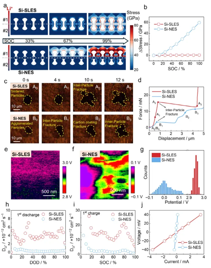
Figure 4. Mechanically reliable and low-resistance sintered interfaces in Si-SLES. (a) Stress distribution in two adjacent particles of Si-SLES and Si-NES at different states of charge. (b) The average stress difference between the two particles at different states of charge. (c) Optical images of Si-SLES and Si-NES post-cycle agglomerates at various loading times in particle indentation tests. (d) Force-displacement curves from particle indentation tests of Si-SLES and Si-NES after 1 cycle. (e,f) KPFM surface potential mappings at the particle interfaces of (e) Si-SLES and (f) Si-NES anodes after 1 cycle. (g) The statistical histograms of surface potential data. (h,i) GITT plots of Si-SLES and Si-NES during the first-cycle (h) discharge and (i) charge process. (j) Current-voltage response obtained from DC polarization of Si-SLES and Si-NES.
Finite element simulation showed a much smaller interparticle stress difference in SLES than in NES, indicating a more uniform stress distribution across the sintered network. The high stress gradients predicted at NES coating interfaces are consistent with localized coating fracture and particle isolation.
Single-particle stiffness tests were performed with the IEST SPFT2000 Single Particle Mechanical Properties Test System using a flat diamond indenter. This system recorded the force-displacement curves until particle fracture. SLES agglomerates sustained a fracture force of 15.7 mN, compared with 3.4 mN for the NES particles. The 4.6-fold difference supports the proposed relationship between selective interparticle bonding and improved mechanical integrity.
KPFM measurements showed a more uniform surface potential across SLES particle boundaries. GITT, DC polarization, EIS, and DRT analyses also indicated faster Li-ion transport and more stable interfacial impedance in SLES. Table 3 consolidates all four particle-level metrics measured for SLES and NES:
| Parameter | Measurement Technique | SLES | NES | Interpretation |
|---|---|---|---|---|
| Interparticle stress difference | FEM simulation | <0.5 GPa | >59.5 GPa | More uniform simulated stress distribution in SLES |
| Single-particle fracture force | IEST SPFT2000 stiffness test | 15.7 mN | 3.4 mN | 4.6-fold higher fracture force for SLES |
| Potential drop at particle boundaries | KPFM | No measurable drop | 50–80 mV | Lower boundary resistance in SLES |
| Li-ion transport | GITT, DC polarization, EIS-DRT | Higher diffusion coefficient and stable impedance | Lower diffusion coefficient and increasing impedance | Faster and more stable transport in SLES |
8. Single-Particle Mechanical Testing with IEST SPFT2000
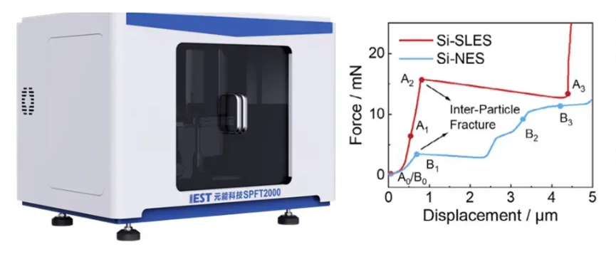
Figure 5. Stiffness testing of SLES and NES particles using the IEST SPFT2000. Left: schematic of the test system. Right: representative force-displacement curves.
The SLES design’s mechanical advantage was quantitatively established through single-particle stiffness testing on the IEST SPFT2000, an instrument specifically designed for mechanical characterization of individual battery material particles in the 5–50 μm size range, compliant with Chinese national standard GB/T 43091-2023. Table 2 lists the key instrument specifications used in this study:
| Specification | Value |
|---|---|
| Applicable particle size range | 5–50 μm |
| Force measurement accuracy | ±0.01 mN (0–100 mN range); ±0.05 mN (0–500 mN range) |
| Displacement resolution | 10 nm |
| Optical imaging magnification | Up to 1200× |
| Particle positioning | Automated XY displacement stage |
| Standard compliance | GB/T 43091-2023 |
Individual SLES and NES agglomerates were tested after one formation cycle. Each particle was positioned beneath the indenter, and a compressive load was applied at a constant displacement rate of 0.5 μm s⁻¹ while the force-displacement curve and optical image were recorded.
The SLES agglomerates exhibited a multistage response before fracturing at 15.7 mN, whereas the NES particles underwent a more abrupt fracture at 3.4 mN. These measurements provide particle-level evidence that the selectively sintered SLES network has greater resistance to compressive failure.
9. Electrochemical Performance in Half-Cells and Full Cells

Figure 6. Electrochemical performance of the Si-SLES anode. (a) Cycling stability of Si-SLES and Si-NES in ASSBs. (b) Cycling stability of Si-SLES and Si-NES in LE. (c,d) Contour map of dQ/dV versus voltage at (c) charging and (d) discharging processes of Si-SLES and Si-NES at different cycling numbers. (e) Rate performance of Si-SLES and Si-NES. (f) Comparisons of the capacity retention rate in the first 100 cycles versus the capacity retention rate at 1C between this work and previously reported results. (g) Cycling test of the Si-SLES || LPSCl || LIC || NCM532 full cell.
The SLES anode was evaluated in ASSB half-cells using a Li–In alloy counter electrode, Li₆PS₅Cl solid electrolyte, and a stack pressure of 50 MPa. The SLES cells retained approximately 100% of their capacity after 100 cycles at 0.2C, compared with 20.6% for NES.
| Test Condition | SLES | NES |
|---|---|---|
| Capacity retention after 100 cycles at 0.2C | ≈100% | 20.6% |
| Coulombic efficiency | >99.5%, stable | Decreased during cycling |
| Rate capability at 1 mA cm-2 (~1C) | 81% of low-rate capacity | Negligible capacity above 0.5 mA cm-2 |
The dQ/dV analysis analysis showed stable peak positions and intensities for SLES over 100 cycles, indicating limited polarization growth. The peaks of the NES cells progressively broadened and shifted, consistent with increasing interfacial resistance and loss of active-material contact.
Critically, when the SLES electrode was tested in liquid electrolyte cells, the advantage over NES disappeared — confirming that the SLES strategy is specifically optimized for the all-solid-state configuration, where solid–solid interface stability is the dominant failure mode.
10. Full-Cell Performance with an NCM532 Cathode
To demonstrate practical viability, the SLES Si anode was paired with a commercial NCM532 cathode in a full-cell configuration using Li₃InCl₆ as the solid electrolyte. The cell maintained over 60% capacity retention after 700 cycles, with stable voltage profiles and no evidence of sudden failure.
The extended cycling results indicated that the SLES network remained functional after its initial formation. The authors attribute this behavior to a self-limiting sintering mechanism: once the interconnected network forms, stress concentration at the pore entrances decreases, reducing the driving force for further sintering and limiting the formation of oversized agglomerates.
11. IEST–NanoYang Joint Laboratory at Tianjin University
The collaborative achievement described in this study builds upon a long-standing research partnership between the Nanoyang research group (led by Professor Yang Quanhong at Tianjin University) and IEST Instrument. On March 23, 2026, this partnership was formalized through the establishment of the IEST–NanoYang Joint Laboratory for Advanced Battery Materials Characterization at Tianjin University. The joint laboratory integrates Nanoyang’s frontier mechanism research in carbon-based energy materials with IEST’s precision characterization instruments, providing a dedicated platform for developing and validating next-generation battery material characterization methodologies.
Related announcement: IEST Instrument and Nanoyang at Tianjin University Establish Joint Laboratory for Advanced Battery Research.
The joint laboratory is strategically positioned to serve as both a showcase for advanced testing instrumentation in the northern China market and as a critical support platform for translating fundamental scientific discoveries into industrial-scale battery solutions. In the present study, the IEST SPFT2000 provided quantitative single-particle force-displacement data for comparing the mechanical response of SLES and NES particles.
12. Conclusions and Outlook
This study showed that electrochemical sintering, often associated with Si-particle agglomeration and electrode damage, can be directed through pore geometry. In the SLES architecture, high-curvature pore entrances concentrate lithiation-induced stress at selected particle contacts. Localized sintering then forms an interconnected Si network, while the internal pores accommodate volume expansion.
The “geometry-guided dynamic evolution” design philosophy demonstrated here has broad applicability beyond silicon anodes. The same principle of using geometric constrictions to concentrate and direct mechanical stress during electrochemical cycling can be extended to other high-volume-change anodes for all-solid-state batteries, including tin (Sn) and lithium metal, offering a generalized pathway toward stable, high-energy-density solid-state energy storage.
🔬 Evaluate Your Silicon Anode Particle Strength with IEST SPFT2000
Quantify single-particle fracture force, crushing strength, and interfacial mechanical properties for your silicon-carbon, hard carbon, or solid electrolyte materials. The IEST SPFT2000 provides ±0.01 mN force accuracy, 10 nm displacement resolution, and compliance with GB/T 43091-2023.
13. FAQs
13.1 What is stress-lens electrochemical sintering (SLES) in solid-state batteries?
SLES is a geometry-guided strategy that uses high-curvature pore openings in a porous carbon host to concentrate the volumetric expansion stress of silicon during lithiation. This concentrated mechanical energy lowers the atomic diffusion barrier at interparticle contacts, inducing selective, local electrochemical sintering. The result is a percolating Si network that is both mechanically robust (49 GPa interface modulus) and ionically conductive. The SLES strategy was developed by Tianjin University and Tsinghua University (DOI: 10.1002/adma.74090) and validated using the IEST SPFT2000 single-particle testing system.
13.2 How does SLES solve the silicon volume expansion problem differently from carbon coating?
Carbon coating physically constrains Si particles but blocks interparticle Li⁺ transport and fractures under cycling stress, leading to delayed but inevitable uncontrolled sintering. SLES, in contrast, actively uses the expansion stress as a constructive force to build a continuous Si network. Instead of preventing sintering, SLES guides it geometrically — the pore opening concentrates stress at the exact locations where sintering is beneficial, building a stable structure with internal voids for expansion buffering while maintaining open ion-transport pathways.
13.3 What performance can SLES silicon anodes deliver in practical all-solid-state batteries?
In half-cells with Li₆PS₅Cl solid electrolyte, SLES anodes deliver ~100% capacity retention over 100 cycles with >81% capacity retention at 1 mA cm⁻². In practical full cells with NCM532 cathodes and Li₃InCl₆ electrolyte, the SLES anode maintains >60% capacity after 700 cycles. These values place SLES among the best-reported silicon anodes for all-solid-state batteries to date.
13.4 What is the difference between electrochemical sintering in liquid-electrolyte cells versus all-solid-state batteries?
In liquid-electrolyte cells, the electrolyte penetrates particle interfaces and provides a separate Li⁺ conduction pathway, so electrochemical sintering is less critical for maintaining ionic connectivity. In all-solid-state batteries, the solid electrolyte cannot penetrate particle contacts — all interparticle Li⁺ transport must occur through direct solid–solid contacts. Therefore, the quality of the sintered interface (modulus, fracture resistance, interfacial resistance) directly determines the cell’s cycling stability. This explains why the SLES advantage disappears in liquid electrolyte cells and is only expressed in the all-solid-state configuration.
13.5 How do I select the right single-particle mechanical testing equipment for battery material characterization?
Selecting single-particle testing equipment depends on required force resolution (sub-mN for most battery materials), displacement precision (sub-μm), and particle size compatibility (5–50 μm for standard electrode materials). The IEST SPFT2000 meets these requirements with ±0.01 mN force accuracy, 10 nm displacement resolution, 1200× optical imaging, and compliance with GB/T 43091-2023. It supports automated XY positioning, multiple test modes (displacement control, pressure loading-unloading, fatigue), and is compatible with glovebox integration for air-sensitive solid electrolyte materials.
