

In this paper, the resistance difference of carbon coated aluminum foils with different formulations and different coating thicknesses is compared by using the electrode resistance test method to analyze the uniformity of their undercoated electrodes.

Figure 1. Schematic diagram of the effect of carbon coated collectors on cell performance.1
Battery Electrode Resistance Tester BER1300 (IEST).
Electrode diameter: 14 mm
Pressure range: 5–60 MPa
Software: MRMS for automated reading of thickness, resistance, resistivity and conductivity
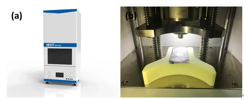
Figure 2. (a) BER1300 appearance; (b) BER1300 structure — used to measure nano-carbon coated aluminum foil sheet resistance and resistivity.
Bare aluminum foil (10 µm)
Two carbon-coated aluminum foils with coating thicknesses of 4 µm and 7 µm
Three primer formulations for the carbon layer
Electrodes after coating with active materials
Each electrode sheet sample was cut into a rectangular size of approximately 5 cm × 10 cm and placed on the sample stage. Test pressure and holding time parameters were set in the MRMS software, and the test was started — the software automatically reads electrode sheet thickness, resistance, resistivity, conductivity, and other data.
Different formulations of carbon coated aluminum foil were tested: bare aluminum foil (10 μm thickness), and two carbon-coated layers at 7 μm and 4 μm respectively. Resistance results for the tested electrodes are shown in Figure 3(a) and (b), revealing that resistance across different formulations of nano-carbon coated aluminum foil varies dramatically — from tens of milliohms to tens of ohms.
Resistance uniformity at different positions within a single electrode also varies substantially between coating processes. Comparing the 4 μm-R(Ω) and 7 μm-R(Ω) datasets, the resistance box plot for the thinner (4 μm) coating is notably wider, indicating poorer resistance uniformity across electrode positions — a pattern associated with coating that is too thin, potential coating leakage points, or uneven carbon material distribution.1


Figure 3. (a) Resistance of carbon coated aluminum foil with 4 μm coating thickness. (b) Resistance of carbon coated aluminum foil with 7 μm coating thickness. (c) Electrode resistivity in three different states: bare foil, carbon coated foil, and electrode with active material.
Analysis of Figure 3(c) shows that bare aluminum foil exhibits the best electrical conductivity, while resistivity of the electrode sheets tested using the two-probe principle increases progressively as the carbon coated layer and active material are added — confirming that the coating introduces contact resistance between particles, weakening overall electron conductivity compared to bare foil. While carbon coating is generally understood to enhance electrode conductivity by increasing aluminum foil surface roughness — which improves contact between active material particles and the collector — this study shows that conductivity uniformity can also be negatively affected when coating thickness is excessive or coating uniformity is poor.
| Sample | Resistivity Trend | Resistance Uniformity | Notes |
|---|---|---|---|
| Bare aluminum foil (10 µm) | Lowest resistivity | — | Best conductivity baseline |
| Nano-carbon coated Al foil (4 µm) | Higher than bare foil | Poor — wide box plot spread | Thin coating prone to leakage / uneven carbon distribution |
| Nano-carbon coated Al foil (7 µm) | Higher than bare foil | Better — narrower box plot spread | Thicker coating improves uniformity |
| Electrode with active material | Highest resistivity | Varies by formulation | Reflects added inter-particle contact resistance |

Figure 4. Schematic representation of the surface morphology of black carbon coated aluminum foil.1
In summary, adding an effective intermediate carbon layer between the active material and the metal collector improves interfacial contact resistance, with several additional potential synergistic benefits:
The chemically and electrochemically stable conductive layer acts as a diffusion barrier, preventing diffusion of oxygen generated by electrolyte decomposition side reactions or lithium-ion embedding processes — effectively preventing formation of an oxidized layer on the metal collector surface and thus preventing degradation.
A well-formulated conductive layer provides good electrical conductivity, enabling a large-area, low-interfacial-resistance contact between the collector and active material coating, facilitating rapid charge transfer.
The flexibility and mechanical cushioning of the conductive layer enhances physical interface adhesion, minimizing the gradual loss of contact area caused by interfacial stresses during long-term cycling. Experimental evidence confirms that well-designed conductive interfacial layers can meaningfully improve electrochemical properties — including specific reversible capacity, capacity retention, and rate performance.
To maximize the advantages of carbon-coated collectors while avoiding conductivity pitfalls:
Optimize formulation: Balance conductive filler type (carbon black, graphene, CNTs) and binder to achieve high surface conductivity and mechanical integrity without creating agglomerates.
Control thickness precisely: Target thickness windows that provide adequate surface roughness and substrate protection without excessive coating thickness that increases inter-particle resistance — this study’s data show 7 μm coatings achieve notably better resistance uniformity than 4 μm coatings.
Ensure coating uniformity: Use inline metrology (thickness mapping, resistivity mapping) and implement process controls to detect and correct coating non-uniformity before it propagates to final electrode performance.
Characterize by position: Perform spatial resistance mapping (box plots per location) rather than relying solely on average resistivity values — local hotspots and thin-coating leakage points often determine real-world failure modes.
Test with active material: Include the final electrode stack (foil + active coating) in qualification testing, since the added active material layer changes macroscopic resistivity relative to the foil alone.
Iterate with electrochemical testing: Combine physical resistance measurements with electrochemical cycle testing to correlate coating metrics with capacity retention, rate performance, and long-term cycling stability.
Carbon coated aluminum foil — whether referred to as nano-carbon coated aluminum foil, carbon coated al foil, or carbon coated aluminum foil — is increasingly adopted as a cathode current collector for its capacity to improve interfacial contact, adhesion, and protection of the aluminum substrate. However, these benefits depend critically on formulation, coating thickness, and — most importantly — coating uniformity. Electrode resistance testing (such as with the IEST BER1300) is an effective QC tool for comparing formulations and processes: this study found resistance varying from tens of milliohms to tens of ohms across formulations, with thinner 4 μm coatings showing markedly worse resistance uniformity than thicker 7 μm coatings. By optimizing carbon type, dispersion, and coating process controls, manufacturers can harness the advantages of carbon coated aluminum foil while helping lithium battery R&D teams reliably monitor undercoated electrode process stability.
[1] Busson, C, Blin, M.A., Guichard, P., Soudan, P., Crosnier, O., Guyomard, D., & Lestriez, B. (2018). A primed current collector for high performance carbon-coated LiFePO4 electrodes with no carbon additive. Journal of Power Sources, 406, 7-17.
[2] Chen Peng, Ren Ning, Ji Xuemin, et al. Investigation on Graphite/LiFePO4 Batteries Fabircated by Carbon-Coated Aluminum Foil Current Collector [J]. New Energy Progress, 2017, 5(2): 157-162.
[3] Li Min, et al.Effect of carbon-coated Al foil on properties of lithium iron phosphate batteries[J]. Energy Storage Science and Technology, 2020, 9(6), 1714-1719.
Nano-carbon coated aluminum foil is aluminum current collector foil with a thin conductive carbon layer — typically conductive carbon black, graphene, or carbon nanotubes — applied to its surface before active material coating. It is used in lithium-ion batteries to reduce interfacial contact resistance between the metal collector and active material particles, improve adhesion and bonding strength of the active layer, and reduce active particle peel-off during electrode cycling. The carbon layer also acts as a diffusion barrier that helps prevent oxidation of the aluminum surface from electrolyte decomposition side reactions, supporting better long-term capacity retention and rate performance.
Carbon coating thickness affects both the absolute sheet resistance and its spatial uniformity. Testing 4 μm and 7 μm nano-carbon coatings on aluminum foil showed that both increase resistivity relative to bare foil, but the thinner 4 μm coating produced a substantially wider resistance distribution across different positions on the same electrode — indicating poorer uniformity. This pattern is associated with thin coatings being more prone to leakage points where the carbon layer is locally too thin, or uneven distribution of carbon material across the foil surface. The thicker 7 μm coating showed a narrower, more consistent resistance distribution.
Carbon coated aluminum foil has higher resistivity than bare aluminum foil — bare foil exhibits the best electrical conductivity of all tested states. When a carbon coated layer is added, and again when active material is subsequently coated on top, resistivity increases progressively at each step, measured using the two-point probe electrode resistance method. This occurs because each added layer introduces additional contact resistance between particles. Despite this, carbon coating is still beneficial overall because it increases aluminum foil surface roughness, improving the physical and electrical contact between active material particles and the collector — provided the coating thickness and uniformity are well controlled.
Resistance uniformity of carbon coated al foil is quantified by measuring resistance at multiple positions across a single electrode sample and analyzing the spread of values, typically visualized as a box plot. An instrument such as the IEST BER1300 — with a 14 mm electrode diameter test fixture, 5–60 MPa pressure range, and MRMS software for automated thickness, resistance, resistivity, and conductivity readout — enables systematic position-by-position resistance measurement on cut electrode samples. A wide box plot spread indicates poor uniformity (associated with coating defects such as thin spots or uneven carbon dispersion), while a narrow spread indicates consistent coating quality across the sample.
Beyond reducing interfacial contact resistance, carbon coated aluminum foil offers three additional synergistic benefits. First, the chemically and electrochemically stable conductive layer acts as a diffusion barrier, preventing oxygen generated by electrolyte decomposition or lithium-ion embedding side reactions from forming an oxidized layer on the aluminum surface — which would otherwise cause degradation. Second, a well-formulated conductive layer enables large-area, low-resistance contact between the collector and active material, facilitating faster charge transfer. Third, the flexibility and mechanical cushioning of the conductive layer enhances physical interface adhesion, reducing gradual contact-area loss from cycling-induced interfacial stress — collectively improving specific reversible capacity, capacity retention, and rate performance.
