

Lithium-ion battery resistance is one of the key indicators for evaluating battery performance. Its magnitude directly influences capacity, cycle life, and safety. Factors affecting lithium-ion battery resistance include electrode materials, formulation, electrolyte, coating uniformity, and intrinsic electrode resistance. Electrode resistance reflects both the performance of the electrode active material and the quality of its coating formulation.
By analyzing electrode resistance test results with the correct measurement method, manufacturers can optimize the coating process and material formulation to enable rapid evaluation of material systems, and quickly identify, classify, and eliminate electrodes with excessively high resistance before they enter cell manufacturing. The choice between the two-point probe method and the four-point probe method for battery electrode resistance is not interchangeable — the two methods measure fundamentally different physical quantities, and selecting the wrong one produces data that cannot differentiate coating quality from foil contribution.
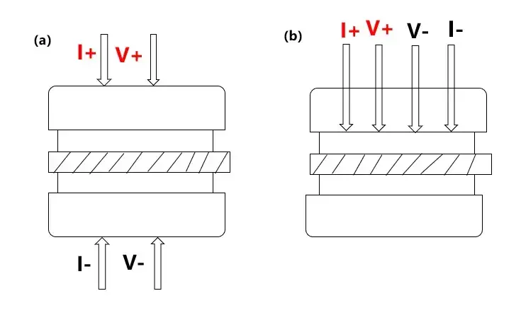
Figure 1. (a) Schematic of the 2 point probe (two-point probe) configuration; (b) Schematic of the 4 point probe (four-point probe) configuration for battery electrode resistance measurement.
In the 2 point probe configuration, the terminal contacts are placed at the vertical ends of the electrode stack, and an AC voltage signal is applied to collect current and calculate resistance. The result is the series sum of contact resistance, coating (active material layer) resistance, and current collector resistance — the total through-plane resistance of the electrode composite. In the 4 point probe configuration, current contacts and voltage-sensing contacts are placed separately on the sample surface, and voltage is measured between the inner contacts while current flows through the outer contacts — eliminating contact resistance but also redirecting current in-plane through whichever path offers lowest resistance.
The IEST BER2500 Battery Electrode Resistance Tester was used for all measurements. The instrument supports both 2 point probe and 4 point probe configurations with a 14 mm electrode diameter measurement fixture and an applied pressure range of 5–60 MPa. The MRMS software automatically records electrode thickness, resistance, resistivity, and conductivity at each test condition.
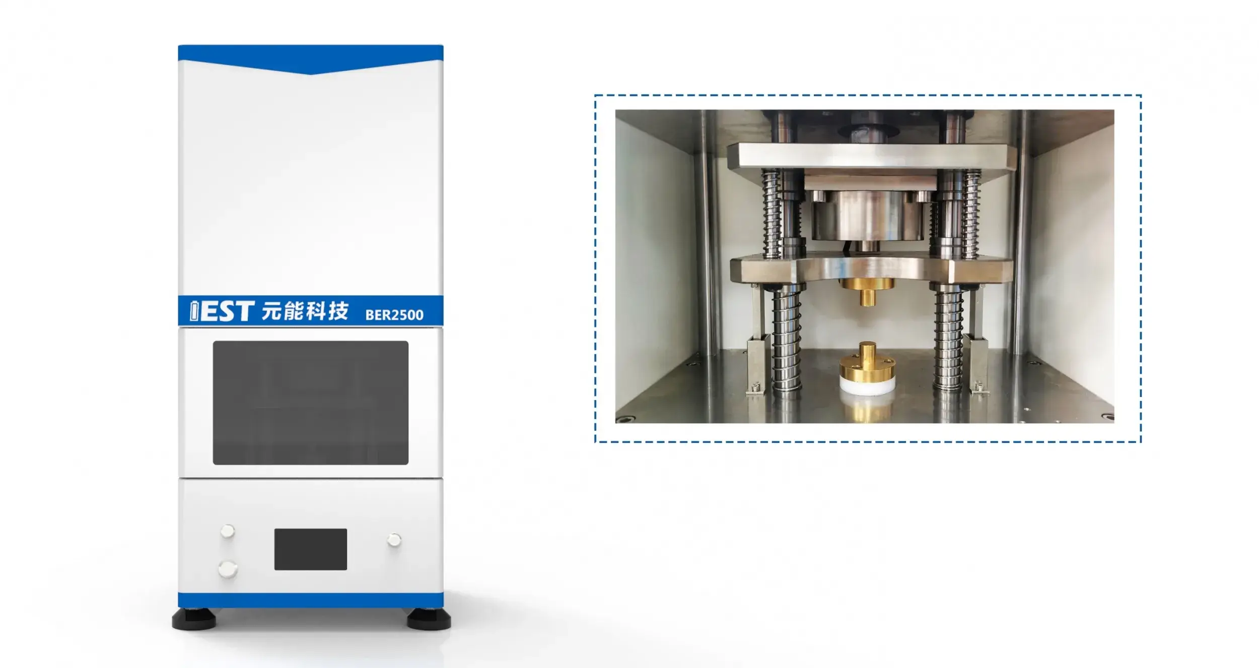
Figure 2. (a) Appearance of the IEST BER2500 Battery Electrode Resistance Tester; (b) BER2500 structural diagram showing electrode fixture and probe configurations.
Seven sample types were tested: cathode electrode cathode-1 (low resistance), cathode electrode cathode-2 (high resistance), anode electrode anode-1 (low resistance), anode electrode anode-2 (high resistance), binder-free pure membrane samples (dry process, single layer and double layer), pure aluminum foil, and pure copper foil.
For cathode electrode resistivity tests (Figure 3), a striking divergence emerges between the two methods when applied to low-resistance electrodes:
Four-point probe method (4 point probe): The resistivity of low-resistance cathode-1 measured by 4-probe (2.1×10⁻⁶ Ω·cm) differed by only approximately one order of magnitude from pure aluminum foil (2.884×10⁻⁵ Ω·cm) — the coating and foil resistivities are so close that the 4-probe measurement cannot reliably distinguish the coating contribution. For high-resistance cathode-2, the 4-probe method yielded 1.3316 Ω·cm, clearly elevated above the foil.
Two-point probe method (2 point probe): The resistivity of cathode-1 measured by 2-probe (1444.94 Ω·cm) was several orders of magnitude greater than the aluminum foil baseline (0.370026 Ω·cm) — a clear, unambiguous separation of coating from foil at all resistance levels. Both cathode-1 and cathode-2 showed resistivity values substantially higher than their respective foil baselines.
 |
 |
Figure 3. (a) Four-point probe cathode electrode resistivity test — cathode-1 approaches foil resistance, making coating indistinguishable; (b) Two-point probe cathode electrode test — coating clearly differentiated from foil baseline at both low and high resistance levels.
Analogous trends were observed for anode electrode resistance (Figure 4). The four-point probe method could not distinguish the influence of the coating layer when testing low-resistance anode samples — the measured resistance closely approached the copper foil baseline — while it did show elevated values for high-resistance anode samples. The two-point probe method, by contrast, clearly revealed resistivity differences between coatings and pure copper foil for both low-resistance and high-resistance anode samples.
 |
 |
Figure 4. (a) Four-point probe anode electrode resistivity test — low-resistance anode coating is indistinguishable from foil; (b) Two-point probe anode electrode test — coating clearly differentiated from copper foil at all resistance levels.
For binder-free pure film samples coated using the dry process, both methods were compared (Figure 5). The 4 point probe measured resistivity of the single-layer film (0.27 Ω·cm) is nearly identical to that of the double-layer film (0.26 Ω·cm) — values far above both aluminum foil (2.884×10⁻⁵ Ω·cm) and copper foil (1.832×10⁻⁵ Ω·cm), because without a metallic current collector substrate, the in-plane current path is also through the film, and the 4-probe result is genuinely the film resistivity. The 2 point probe measured resistivity of single-layer film (1.27 Ω·cm) and double-layer film (1.23 Ω·cm) are closely comparable but consistently higher than the 4-probe values — reflecting the additional contact resistance term captured by the 2-probe method.
This result explains why the four-probe method does produce reliable resistivity data when measuring self-standing film electrodes without a foil substrate — the only case where the metallic bypass path (path 2) is absent.

Figure 5. Pure membrane (binder-free, dry-process film) resistivity measurement by 4 point probe vs 2 point probe. Single-layer: 0.27 Ω·cm (4-probe) vs 1.27 Ω·cm (2-probe). Double-layer: 0.26 Ω·cm vs 1.23 Ω·cm. Without a foil substrate, the 4-probe method accurately measures film resistivity.
The equivalent circuit analysis of both probe configurations (Figure 6) explains the divergent results:
Two-point probe circuit (Figure 6a): Current and voltage terminals are at the vertical (through-plane) ends of the electrode stack. The measurement result is the total series sum of: contact resistance (Rcontact) + coating layer resistance (Rcoating) + current collector (foil) resistance (Rfoil). Because the coating resistance of most battery electrodes is far higher than the foil resistance, the total measured resistance is dominated by the coating — making the 2-probe method inherently sensitive to coating quality and batch variation.
Four-point probe circuit (Figure 6b): Applied current enters through two outer surface contacts and can flow via three paths — path 1 (through the coating layer vertically), path 2 (horizontally through the metallic current collector), or path 3 (diagonal combinations). For low-resistance electrodes where the foil resistance is comparable to or lower than the coating resistance, electrons predominantly flow through path 2. The voltage measured between the inner contacts therefore reflects primarily the foil resistance — not the coating. This is why the 4-probe result for cathode-1 (2.1×10⁻⁶ Ω·cm) was close to pure aluminum foil (2.884×10⁻⁵ Ω·cm). Only when the coating resistance is very high (cathode-2: 1.3316 Ω·cm) does path 1 carry appreciable current, making the 4-probe measurement coating-sensitive.
Furthermore, because the absolute resistance values measured by the 4-probe method are very small (often below 1 Ω for foil-backed electrodes), extremely high requirements are imposed on instrument precision, measurement range, and pressure control stability — making reliable, repeatable data difficult to obtain under practical laboratory conditions.
 |
 |
Figure 6. Equivalent circuit diagrams. (a) Two-point probe: current passes through the full vertical stack — contact resistance + coating + foil in series. (b) Four-point probe: current divides into three paths; for low-resistance electrodes, path 2 (through foil) dominates, masking coating contribution.
| Comparison Item | 2 Point Probe (Two-Probe) | 4 Point Probe (Four-Probe) |
|---|---|---|
| What is measured | Total through-plane resistance: Rcontact + Rcoating + Rfoil | In-plane surface resistance; foil-dominated for low-resistance electrodes |
| Sensitivity to coating (low resistance) | ✓ Clearly distinguishes coating from foil at all resistance levels | ✗ Measurement converges to foil resistance — coating invisible |
| Sensitivity to coating (high resistance) | ✓ Clearly elevated above foil | ✓ Elevated above foil when \(R_{contact} + R_{coating} + R_{foil}\) |
| Cathode-1 result vs Al foil | 1444.94 Ω·cm vs 0.370026 Ω·cm — clear differentiation | \(2.1 \times 10^{-6}\ \Omega\cdot\mathrm{cm}\) vs \(2.884 \times 10^{-5}\ \Omega\cdot\mathrm{cm}\) — ~1 order of magnitude only |
| Contact resistance | Included (upper bound of true coating resistance) | Excluded (advantage for material intrinsic resistivity) |
| Instrument precision requirement | Moderate — measured values in Ω·cm range | Very high — small absolute values require high-stability pressure control |
| Applicable to foil-backed electrodes | Yes — all cathode and anode types | Partially — reliable only for high-resistance or freestanding films |
| Applicable to pure/freestanding films | Yes | Yes — no foil bypass path |
| Recommended application | Battery electrode QC, process optimization, R&D screening | Material intrinsic resistivity research; freestanding films |
This study demonstrates that the two-point probe method is the appropriate choice for measuring electrode resistance in lithium-ion battery cathodes and anodes. The 2-probe method measures total through-plane resistance — capturing the composite of contact, coating, and foil contributions — and reliably differentiates coating quality from foil baseline at all resistance levels. The four-point probe method, while eliminating contact resistance, causes current to bypass the coating through the metallic foil in low-resistance electrodes, rendering the coating contribution invisible. Only when the electrode coating resistance substantially exceeds the foil resistance (typically high-resistance or degraded samples) does the 4-probe method become coating-sensitive — and even then, the small absolute values demand high instrument precision and pressure control stability. For production screening, process optimization, and material formulation evaluation of foil-backed battery electrodes, the 2 point probe method provides more reliable, actionable resistance data.
[1] Hiroki Kondo et al. Influence of the Active Material on the Electronic Conductivity of the Positive Electrode in Lithium-Ion Batteries. Journal of The Electrochemical Society, 2019,166 (8) A1285-A1290
[2] B.G.Westphal et al. Influence of high intensive dry mixing and calendering on relative electrode resistivity determined via an advanced two point approach. Journal of Energy Storage 2017, 11, 76–85
[3] Nils Mainusch et al. New Contact Probe and Method to Measure Electrical Resistances in Battery Electrodes. Energy Technology.2016, 4, 1550-1557
The key difference between the two-probe and four-probe methods for battery electrode resistance is what each measurement captures. The two-point probe method applies current and voltage at the vertical (through-plane) ends of the electrode stack, measuring the total series resistance of contact layers, active material coating, and metallic current collector. The four-point probe method places current and voltage contacts separately on the electrode surface, routing current in-plane and eliminating contact resistance — but this also allows current to bypass the coating through the highly conductive metallic foil. For low-resistance electrodes on aluminum or copper foil, the four-probe measurement therefore approaches the foil baseline, making the coating contribution invisible. The two-probe method is sensitive to the coating at all resistance levels and is the recommended choice for battery electrode quality control.
Use the 2 probe (two-point probe) method for electrode resistance measurement whenever the electrode consists of an active material coating on a metallic foil substrate — which describes the vast majority of lithium-ion battery cathode and anode electrodes. The 2-probe method’s through-plane measurement captures coating resistance independently of the foil’s in-plane conductivity, reliably distinguishing low- and high-resistance coatings at all levels. Use the 4 point probe method when measuring the intrinsic resistivity of freestanding electrode films without a foil substrate, or when comparing material-level resistivity of powders and pure films where contact resistance elimination is critical and no metallic bypass path exists.
The four-point probe method fails for low-resistance battery electrodes because the measurement current divides between three parallel paths at the electrode surface: path 1 through the active material coating, path 2 through the highly conductive metallic current collector (aluminum or copper foil), and diagonal combinations. When electrode coating resistance is low (comparable to or only slightly higher than the foil’s in-plane resistance), electrons predominantly travel through path 2 — the metallic foil — bypassing the coating entirely. The measured voltage reflects primarily the foil resistance rather than the coating. For cathode-1, the 4-probe result (2.1×10⁻⁶ Ω·cm) was within one order of magnitude of pure aluminum foil (2.884×10⁻⁵ Ω·cm), providing no usable coating quality information. The 2-probe method avoids this problem by directing current through the full electrode thickness, forcing it to pass through the coating.
The two-point probe method measures the total through-plane resistance of a battery electrode — the series sum of contact resistance at both electrode faces, active material coating resistance, and current collector (foil) resistance. Because the active material coating typically has resistivity several orders of magnitude higher than the metallic foil, the total resistance measured by the 2-probe method is dominated by the coating contribution. This makes two-probe resistivity measurement directly sensitive to coating formulation, conductive additive loading, calendaring conditions, and batch-to-batch material variation — the parameters that battery manufacturers need to monitor and control in cathode and anode electrode production.
For the same battery electrode, the 2-probe resistivity value is always higher than the 4-probe value — because the 2-probe measurement includes contact resistance and measures only through-plane current flow, while the 4-probe measurement eliminates contact resistance and allows in-plane bypass through the foil. For a binder-free pure film sample (no foil), this study measured 1.27 Ω·cm (2-probe) vs 0.27 Ω·cm (4-probe) for the single-layer film — a factor of approximately 4.7× difference attributable to the contact resistance term. For foil-backed low-resistance electrodes, the divergence is even more dramatic: the 4-probe value can approach the foil baseline while the 2-probe value clearly shows the coating contribution.
