-
iestinstrument

Abstract
1. What is a Three Electrode System / Three Electrode Cell?
A three electrode system is an electrochemical configuration consisting of a Working Electrode (WE), Counter Electrode (CE), and Reference Electrode (RE). Unlike two-terminal setups, the 3 electrode system decouples potential measurement from current flow. This separation eliminates voltage drop errors, ensuring precise control and accuracy in advanced battery diagnostics including EIS, CV, and GITT.
The system operates through three distinct components — the Working Electrode (WE), the Counter Electrode (CE), and the Reference Electrode (RE) — each with a precisely defined and non-interchangeable role:
-
Working Electrode (WE) — the electrode under study where the electrochemical reaction of interest occurs.
-
Counter Electrode (CE) — also called the auxiliary electrode; it completes the current path and supplies or balances current.
-
Reference Electrode (RE) — a non-polarizable electrode that provides a stable reference potential against which the WE potential is measured.
By separating current control from potential measurement, the three electrode cell allows researchers to independently control the working electrode’s potential while the counter electrode handles the system current, providing unmatched experimental accuracy compared to two-electrode setups.
2. Roles & Requirements of the Working Electrode, Counter Electrode, and Reference Electrode
Each of the three electrodes — the working electrode, counter electrode, and reference electrode — carries a distinct responsibility. Understanding what the working electrode, counter electrode, and reference electrode each do is the starting point for designing a reliable electrochemical experiment.
2.1 Working Electrode (WE)
The WE is the focus of all experiments. It must be chemically inert relative to the electrolyte, present a reproducible surface, and have a controlled geometric area. Common working electrodes include glassy carbon, platinum, gold, conductive oxides (FTO/ITO), and composite battery electrodes prepared as test coupons. All electrochemical signals of interest originate at the working electrode surface.
2.2 Counter Electrode (CE)/Auxiliary Electrode
The counter electrode — also termed the auxiliary electrode — must be large, highly conductive, and chemically stable (typically platinum mesh or graphite rod). Its sole function is to counterbalance the electron flow driven through the working electrode, allowing the potentiostat to maintain the target WE potential accurately. The counter electrode carries all the cell current so that the reference electrode branch draws none.
2.3 Reference Electrode (RE)
The reference electrode provides a stable, reproducible voltage reference (common examples: Ag/AgCl, saturated calomel electrode — SCE). Because the RE branch draws negligible current, its equilibrium potential remains constant regardless of what is happening at the working electrode. This allows the potentiostat to measure and control working electrode potential with millivolt-level precision against a known, fixed baseline.
3. Why is the Three Electrode System So Important?
In the early days of electrochemical research, experiments relied on two-electrode systems. Although straightforward, the two-electrode setup had significant limitations in measuring and controlling electrode potentials, leading to systematic errors. In the 1920s, electrochemists introduced the reference electrode, thereby creating the 3 electrode system. This innovation substantially improved the precision and reproducibility of electrochemical measurements. The three electrode system delivers two key advantages over two-electrode configurations:
3.1 Precise Potential Control
The reference electrode allows independent measurement and control of the working electrode potential without interference from the current flowing in the counter electrode branch. This independence is particularly critical when studying the kinetics and mechanisms of electrochemical reactions, because even small potential errors introduce exponentially large errors in rate constants via the Butler–Volmer equation.
3.2 Improved Accuracy in Complex Systems
In a two-electrode setup, voltage drops from solution resistance (IR drop) and counter electrode polarization obscure the true working electrode potential. The three electrode cell largely eliminates this ambiguity: the reference electrode provides a stable potential baseline, allowing clear separation and analysis of the different electrochemical processes within the system — including interfacial charge transfer, diffusion layers, and film formation kinetics.
3.3 Two-Electrode vs. Three-Electrode System: Side-by-Side Comparison
| Parameter | Two-Electrode System | Three-Electrode System | Implication for Battery Research |
|---|---|---|---|
| Electrode count | WE + CE only | WE + CE + RE | RE enables isolated WE potential control |
| Potential control | Applied across both electrodes; CE polarization adds error | WE potential set vs. stable RE; CE handles current | Critical for studying SEI formation windows (<100 mV range) |
| IR drop error | Included in measured voltage; cannot be separated | Uncompensated resistance (Ru) measurable and correctable via EIS | Accurate impedance spectra require Ru separation |
| CE polarization effect | Directly distorts WE measurement | Isolated from measurement branch | Prevents false kinetic parameters in CV peak analysis |
| Typical application | Simple charge/discharge cycling; production-line testing | EIS, CV, GITT, PITT; kinetic & mechanistic R&D | Lab-stage material development requires 3-electrode precision |
| Potentiostat required | No (galvanostat sufficient) | Yes — requires high-impedance RE input (>10 GΩ) | IEST analyzers provide >10 GΩ RE input impedance |
4. How a Three Electrode Cell Is Connected — the “Two-Circuit” Concept
A three electrode system is operated with an electrochemical workstation (potentiostat/galvanostat). Conceptually, the three electrode cell forms two distinct circuits running in parallel:
-
Potential measurement circuit: high-impedance voltmeter between WE and RE — measures and controls working electrode potential with negligible current draw on the RE.
-
Current supply circuit: ammeter and current source between WE and CE — delivers or extracts the current required to maintain the target WE potential.
This “three-electrode, two-circuit” arrangement is the foundation for experiments such as cyclic voltammetry (CV), electrochemical impedance spectroscopy (EIS), galvanostatic intermittent titration technique (GITT), and potentiostatic intermittent titration technique (PITT). Without the reference electrode branch to fix the potential reference point, the 3 electrode potentiostat cannot accurately distinguish working electrode kinetics from counter electrode polarization.
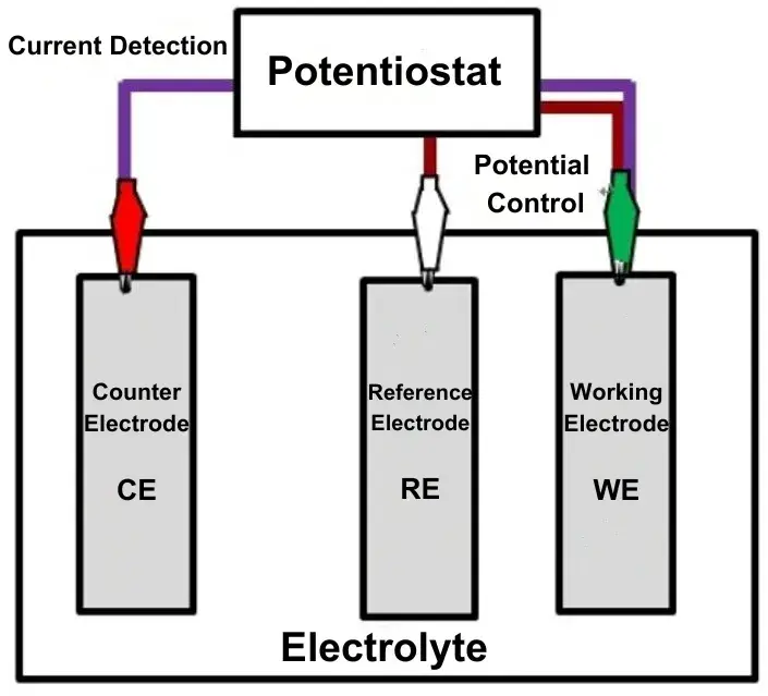
Figure 1. Structure of the three electrode system: working electrode (WE), counter electrode (CE), and reference electrode (RE) wiring in a two-circuit potentiostat configuration
5. Practical Tips for Effective Three-Electrode Measurements
-
Reference placement: Position the RE tip as close to the WE surface as possible (Luggin capillary geometry) to minimize uncompensated resistance Ru and reduce IR drop error in EIS high-frequency data.
-
Counter electrode sizing: Use a CE with surface area at least 5–10× larger than the WE to prevent CE polarization from limiting current supply and distorting WE potential control.
-
Surface preparation: Standardize WE polishing (0.05 μm alumina for glassy carbon), rinse sequence, and equilibration time before each run — surface state variability is the leading cause of poor CV reproducibility.
-
IR compensation: Apply potentiostatic EIS at open circuit to determine Ru, then apply positive feedback compensation in CV and GITT protocols. Avoid over-compensation — Ru overshoot causes instability oscillations.
-
Cell geometry: Use appropriate cell designs (beaker cell for exploratory work, Swagelok or coin-cell adaptors for battery electrodes, T-cell for symmetric electrode studies) matched to the material geometry and electrolyte volume requirements.
In electrochemical research, particularly in battery-related studies, the three electrode system has become the standard laboratory configuration. However, to fully leverage the advantages of the three electrode cell, high-precision electrochemical analyzers are essential. The following sections detail the specific instrument requirements and how the IEST Electrochemical Analyzer addresses each.

Figure 2. Three electrode cell measurement performed with the IEST Electrochemical Analyzer
6. Precise Potential Control in a Three Electrode System
The reference electrode in the 3 electrode system provides a stable potential baseline for precise control of the working electrode. High-precision electrochemical workstations must maintain potential stability even at sub-microampere current levels — the regime critical for studying SEI film formation on lithium-ion battery negative electrode materials.
The SEI formation window on graphite anodes typically spans a narrow potential range (approximately 0.5 V to 0.05 V vs. Li/Li⁺), within which multiple overlapping reduction reactions occur. Resolving these reactions by CV or GITT requires potential accuracy at the microvolt level. The IEST Electrochemical Analyzer controls and measures potential changes with accuracy within ±100 μV, enabling reliable differentiation of SEI formation sub-steps that would be indistinguishable on lower-precision instruments.
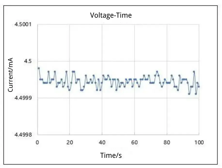
Figure 3. Voltage control in a three-electrode setup: setpoint 4.5 V, measured value 4.5 V ± 100 μV
7. Accurate Current Measurement in a Three Electrode Cell
Understanding the dynamics and mechanisms of electrode reactions requires precise measurement of current responses. In CV testing on battery electrode materials, researchers must resolve peak currents that can be as small as a few nanoamperes for thin-film or low-loading test coupons. The IEST Electrochemical Analyzer provides current measurement resolution at the nanoampere (nA) level with overall current accuracy of ±0.01% FS across all measurement ranges.
This precision level matters in practice because CV peak current ratios ($i_{pa}/i_{pc}$) and peak potential separations ($\Delta E_p$) are used to extract diffusion coefficients, rate constants, and reversibility indicators for electrode materials. A current accuracy error of 0.5\% or greater introduces proportional errors in all derived kinetic parameters — making sub-0.05\% measurement accuracy a practical necessity rather than a specification marketing point.
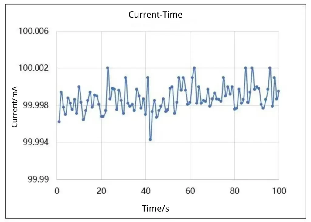
Figure 4. Current control in a three-electrode system: setpoint 100 mA, measured value 100 mA ± 5 μA
8. Low-Noise Characteristics for EIS in Three-Electrode Setup
Electrochemical signals in three electrode cells are frequently very weak — particularly in the sub-nanoampere current range associated with trace reaction monitoring or thin-film electrode characterization. External electromagnetic interference, ground loops between the potentiostat and the cell, and thermal noise at the working electrode input amplifier all degrade signal quality.
The IEST Electrochemical Analyzer‘s EIS module maintains noise floors below the minimum required measurement threshold across the full frequency range of 0.01 Hz to 100 kHz. In EIS measurements, high-frequency noise (above 10 kHz) distorts the semicircle associated with charge-transfer resistance (\(R_{ct}\)) and double-layer capacitance (\(C_{dl}\)), leading to systematic underestimation of \(R_{ct}\). The IEST integrated low-noise EIS design resolves these high-frequency features accurately, supporting reliable equivalent-circuit fitting and SEI film characterization in three-electrode cell configurations.
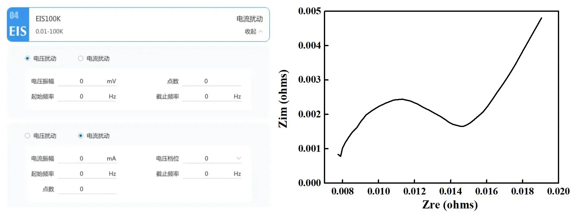
Figure 5. EIS setup steps and impedance spectrum on the IEST Electrochemical Analyzer using a three-electrode configuration
9. Wide Frequency Response Range for Three-Electrode EIS
Electrochemical impedance spectroscopy in a three electrode cell probes processes spanning many decades of frequency:
-
High frequency (1 kHz – 100 kHz): Solution resistance ($R_s$), inductive response of leads, and charge-transfer kinetics at the electrode–electrolyte interface.
-
Mid frequency (1 Hz – 1 kHz): Charge-transfer resistance ($R_{ct}$), double-layer capacitance ($C_{dl}$), and SEI film impedance.
-
Low frequency (0.01 Hz – 1 Hz): Solid-state lithium-ion diffusion within active material particles, expressed as the Warburg impedance element.
The IEST Electrochemical Analyzer covers the full 0.01 Hz to 100 kHz frequency range in a single EIS sweep with consistent phase accuracy throughout. This breadth allows a single measurement protocol to capture both the solid-state diffusion information needed for lithium-ion diffusion coefficient ($D_{Li^+}$) calculation and the high-frequency charge-transfer data needed for interfacial kinetic modeling, without requiring separate instruments or cell re-assembly.
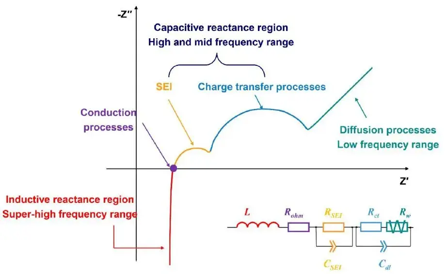
Figure 6. Physical and chemical properties of electrochemical systems characterized by EIS across different frequency ranges (0.01 Hz–100 kHz)
10. Multi-Functional Integration: CV, EIS, GITT, and PITT in One Platform
The IEST Electrochemical Analyzer integrates the following electrochemical test techniques in a single instrument, compatible with three electrode cell configurations:
-
Cyclic voltammetry (CV) — redox peak identification, reaction reversibility assessment, and electroactive surface area determination.
-
Electrochemical impedance spectroscopy (EIS) — interfacial resistance, diffusion parameters, and equivalent-circuit model fitting.
-
Galvanostatic intermittent titration technique (GITT) — chemical diffusion coefficient (DLi⁺) determination during charge/discharge by measuring the transient and equilibrium voltage response to current pulses.
-
Potentiostatic intermittent titration technique (PITT) — complementary diffusion coefficient measurement under potential-step control, resolving the current transient decay to quantify lithium solid-state diffusion.
11. Data Processing and Analysis for Three-Electrode Measurements
The IEST Electrochemical Analyzer provides real-time data processing and multi-dimensional analysis of complex electrochemical data sets generated in three electrode cell experiments. Key capabilities include:
-
Automated equivalent-circuit fitting for EIS spectra (Randles circuit and modified variants including SEI film elements).
-
GITT diffusion coefficient calculation with automated pulse integration and equilibrium potential extraction.
-
CV peak detection, integration for charge quantification, and scan-rate-dependent analysis for determining diffusion- vs. capacitive-controlled contributions.
-
Multi-channel synchronized data acquisition for parallel three-electrode experiments, supporting statistical comparison across replicate cells.
Hardware parameters alone are not the primary limiting factor in current electrochemical workstation performance — circuit optimization improves results to a degree, but the more pressing need is intelligent data analysis software that moves beyond raw data display toward automated extraction of physically meaningful parameters. The IEST platform continues development in this direction, with ongoing software updates targeting automated anomaly flagging and parameter trend monitoring across charge–discharge histories.
Need Precision Three-Electrode Measurements?
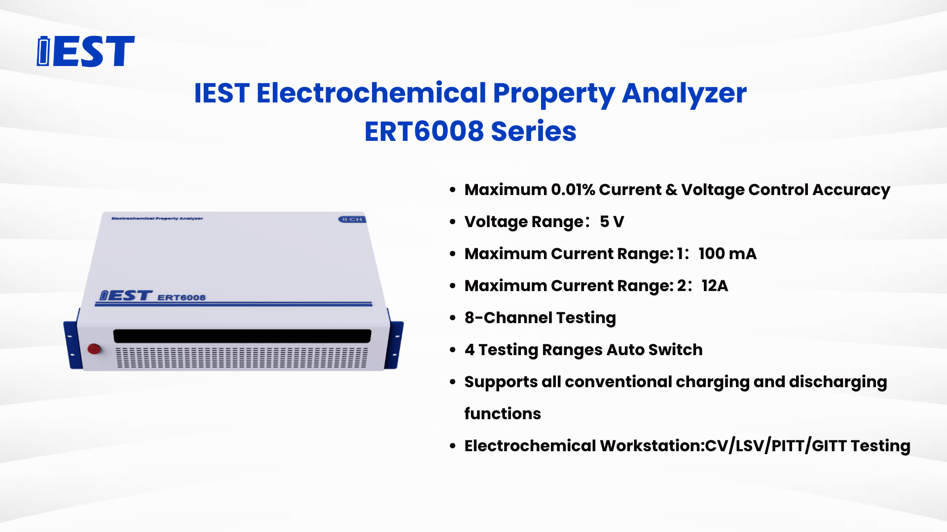
The IEST ERT Series Electrochemical Analyzer supports three electrode cell configurations with ±100 μV potential accuracy, nA-level current resolution, and an integrated EIS module covering 0.01 Hz to 100 kHz — meeting R&D-grade precision requirements for EIS, CV, GITT, and PITT battery diagnostics.
11. Summary
The three electrode system — comprising the working electrode, counter electrode, and reference electrode — is the foundational laboratory configuration for precision electrochemical research. Although the three-electrode structure is invisible in finished battery cells, it plays a critical role at the material development and characterization stage:
- EIS measurements in a three electrode cell resolve impedance contributions from the SEI film, charge-transfer resistance, and solid-state diffusion — each at a different frequency range.
- CV measurements in a three-electrode setup provide redox reaction mechanisms, peak potentials, and kinetic parameters for electrode materials.
- GITT and PITT measurements in the three electrode system yield chemical potential curves and solid-state diffusion coefficients, enabling material design optimization.
The introduction of the reference electrode into the 3 electrode system in the 1920s transformed electrochemical science by enabling potential-resolved studies of complex interfacial processes. As battery materials become more sophisticated — high-voltage cathodes, conversion anodes, solid electrolytes — the precision demands on three electrode cell measurements only increase. Instruments capable of sub-100 μV potential accuracy, nA current resolution, and integrated multi-technique operation are no longer optional; they are the prerequisite for generating data that supports publication-grade mechanistic conclusions.
13. FAQs About the Three Electrode System
What is a three electrode system and its components?
A three electrode system is an electrochemical configuration used for precise measurements. It consists of a Working Electrode (WE) where the reaction occurs, a Counter Electrode (CE) that completes the current circuit, and a Reference Electrode (RE) that provides a stable potential baseline. The three electrode cell ensures precise control in advanced battery diagnostics including EIS, CV, and GITT.
What is the working principle of a three electrode system?
A three electrode system achieves precise electrochemical measurement by separating the current path (working electrode–counter electrode) from the potential measurement path (working electrode–reference electrode). The reference electrode provides a stable potential reference; the working electrode hosts the reaction of interest; and the counter electrode completes the current loop. This two-circuit design eliminates potential measurement errors caused by current flow — the fundamental problem in two-electrode systems — and is essential for accurate CV and EIS data.
What is the difference between a 2-electrode and a 3-electrode system?
Structure: A two-electrode system has only a working electrode and a counter electrode; a three electrode system adds an independent reference electrode.
Accuracy: A three-electrode setup allows precise control of working electrode potential, avoiding IR drop and CE polarization errors.
Application: Two-electrode setups are suitable for simple battery cycling tests; three-electrode systems are used for reaction mechanism studies, kinetic analysis, EIS, CV, GITT, and PITT.
Measurement: The three electrode cell enables independent measurement of working electrode potential, separating anodic and cathodic processes.
What is the role of the counter electrode (auxiliary electrode) in a three-electrode setup?
The counter electrode — also known as the auxiliary electrode — completes the current path in the three electrode cell. Its function is to supply or absorb electrons at an equal and opposite rate to the working electrode, so the potentiostat can maintain the target WE potential. The counter electrode plays no role in the potential measurement. For high-precision measurements, the counter electrode surface area should be at least 5–10× that of the working electrode to avoid polarization.
Why is a high-precision analyzer required for 3-electrode measurements?
To fully leverage a three electrode system, electrochemical analyzers must provide microvolt-level (±100 μV) potential control and nanoampere-level current measurement (±0.01% FS accuracy). These specifications are critical for resolving minute electrochemical changes — such as SEI formation sub-steps on lithium-ion battery anodes — that occur within narrow potential windows and at sub-microampere current levels during EIS and CV tests. The IEST ERT Series Electrochemical Analyzer meets these precision requirements with an integrated EIS module covering 0.01 Hz to 100 kHz.
What is the difference between the working electrode and the counter electrode?
The working electrode hosts the electrochemical reaction under study and its potential is precisely controlled by the potentiostat. The counter electrode completes the current circuit, supplying or absorbing electrons so the working electrode potential remains stable. Critically, the counter electrode participates in no measurement — all electrochemical information is extracted from the working electrode response measured against the reference electrode. When people search “working electrode vs counter electrode,” the core distinction is: the working electrode is measured; the counter electrode is only a current path.
