-
iestinstrument
Quantitative Characterization Of The Effect Of Processing Techniques On Silicon-based Anode Materials
1. Preface
This paper focuses on quantifying the extent of pressure damage to the material by using different pressures to flat-press silicon-based anode materials powders after calendering and making slurries, and monitoring their slurry gas production.
Lithium-ion battery anode and cathode materials are typical powder substances, and their characteristics are directly related to the battery performance. The shape, particle size, specific surface area, internal structure, filling density, surface properties and other factors of the electrode powder have a great influence on the energy density, output characteristics and cycle characteristics of the battery. Therefore, the design and processing of electrode materials has become an important issue. In short, the electrode material determines the upper limit of the battery performance, while the process determines the lower limit of its performance, so it is necessary to improve the process as much as possible to reduce the difference between the upper and lower limits of performance.
Surface coating is one of the commonly used and effective methods to modify positive and negative electrode materials, which can effectively block the direct contact with electrolyte, reduce the occurrence of side reactions with electrolyte, and also stabilize the structure, reduce the phase transition stress, and improve the cycling stability of the battery cell. However, in the actual production of the electric core, it is necessary to go through very complicated processes, such as homogenizing with a high-speed rotary mixer and pressing the electrode sheet with a large pressure roller, etc. These processes are prone to a series of problems, such as shedding of the coating layer, crushing of the particles, cracking of the coating, and even changes in the structure of the material, which will affect the performance of the electric core in terms of its capacity and life span. In particular, in Si-based composites, electrode calendering leads to fracture of particles in the composite, collapse of the porous design structure, and rupture of the outermost carbon cladding layer used to stabilize the composite. As a result, electrode calendering leads to severe degradation of cell performance.
2. Test Information
2.1 Experimental equipment
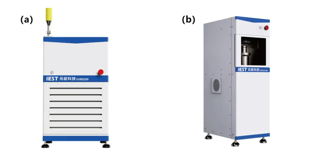
Test equipment 1: IEST In-situ gas production volume monitor, model GVM2200;
Test equipment 2: IEST Powder resistivity & compaction density tester, model PRCD3100.
Figure 1. (a) In-situ gas production volume monitor (GVM2200); (b) Powder resistivity & compaction density tester (PRCD3100)
3. Experimental Process And Analysis
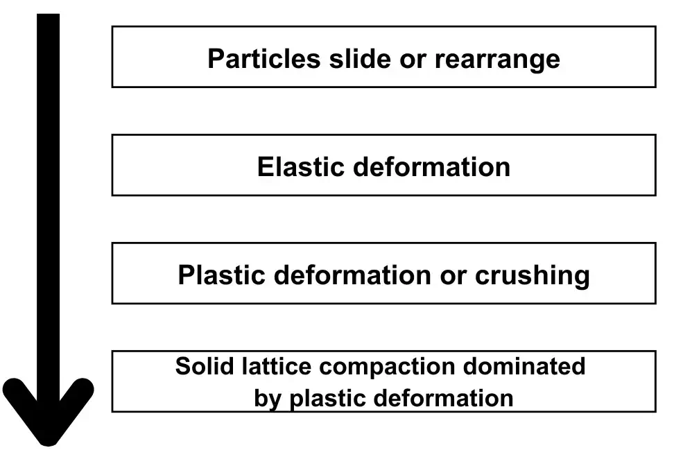
Lithium cathode and anode materials belong to the powder materials, powder materials in the compression process will go through the four processes shown in Figure 2: compression of the initial period of inter-particle sliding or rearrangement to find a more compact stacking. This process is mainly dependent on the friction and interaction forces between the particles. As the pressure continues to increase the particles undergo elastic and plastic deformation. If the pressure is increased further, in extreme cases exceeding its tolerance limit, the particles may be broken or pulverized. In short, powder particles have a significant impact on the structure of the material itself during these evolutionary processes.

Figure 2. Microscopic change process of powder material under pressure
3.1 Resistivity and compaction density
Silicon-carbon anode powder were selected, divided into four groups of parallel samples, weighed 1.0g, and then the powder resistivity & compaction density tester (PRCD3100) of IEST was used to monitor the changes of conductivity and compaction density under different pressure conditions at 10MPa, 50MPa, 100MPa, and 200MPa, as shown in Figure 3(a): four parallel samples As the pressure increased, the conductivity and compacted density showed an increasing trend. Figure 3(b) shows the trend of the compacted density and conductivity of the samples during the whole process from 0 to 200 MPa, and the whole process also shows the phenomenon that the compacted density and conductivity increase with the increase of pressure.
![]()
Figure 3. Variation curves of conductivity and compacted density under different pressures of Silicon-carbon anode powder
From Figure 2, we know that the powder material will be subject to strong interactions between particles when it is pressurized, and the particles will be rearranged, the cladding layer will fall off, and even changes such as crushing will occur. These phenomena are related to the mechanical contact stress between particles, elastic-plastic deformation of particles, friction and surface energy, etc. Specifically, it is necessary to take into account the plastic energy of the particle material, Young’s modulus, yield strength, strain hardening and other material properties. Combined with the trend of Figure 3, the results indicate that only a very small portion of the particles with cladding layer detachment and particle fragmentation may have occurred in this sample during compression, and the changes did not affect the electronic conductive pathway and the overall thickness, i.e., such a small amount of cladding layer detachment and particle fragmentation is not significantly correlated with the electrical conductivity and the compaction density.
3.2 Microstructure
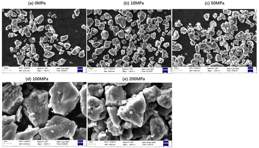
The microstructure was observed by scanning electron microscope (SEM), in which the 0MPa sample is the unpressurized sample, as shown in Figure 4:The microstructure of the sample is not significantly different from the unpressurized sample before 50MPa, and when the pressure reaches 100MPa, the particles can be found broken in the field of view. Generally, silicon particles have a Young’s modulus of 150 GPa and a yield strength of 0.5 to 2 GPa, while graphite materials have a Young’s modulus of 50 GPa and a yield strength of about 0.5 GPa.During the compression of the particles, the stress-strain curves can be plotted by applying a compressive load and measuring the changes in strain and stress. The compression stress-strain curve usually has the following characteristics: (1) Elastic phase, at the beginning of the applied load, the material will undergo elastic deformation, that is, the strain is proportional to the stress. The slope of this phase represents the stiffness of the material. (2) Yield phase, when the load continues to increase, the material undergoes plastic deformation, i.e., the strain is no longer proportional to the stress. In this stage, the material will reach a maximum value of stress, which is the yield strength. (3) Plastic phase After the yield point, the material will undergo continuous plastic deformation. The stress will gradually decrease as the strain increases. (4) Fracture stage, when the stress reaches the ultimate strength of the material, the material will fracture. At this time, the strain will increase sharply and the stress will decrease rapidly. The appearance of cracks in the particles indicates that the material is beginning to fracture and the compression force exceeds the ultimate strength of the material. In this case, the electrode particles cannot maintain the original shape and stability, and the electrode performance will deteriorate.

Figure 4. Microstructure under different pressure conditions
3.3 Slurry Gas Production
Although the effect of pressure on the fragmentation of silicon-based particles can be discerned to some extent by microstructure, the distinction is not obvious and difficult to quantify. Given that elemental silicon hydrolyzes readily, producing gaseous hydrogen, and that a common surface modification method for silicon-based materials (surface cladding) is to use silicon as the core with one or more layers of carbon cladding around the periphery, it is possible to use silicon-based slurry outgassing to quantitatively assess the effect of the additive process on the structure of the material.
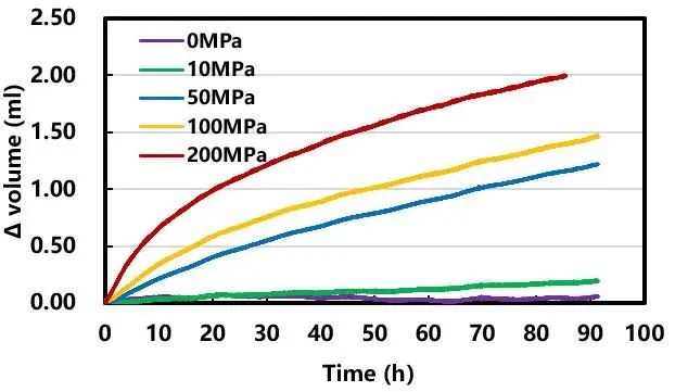
According to the mass ratio of 1:5 (silicon: deionized water) mixed and sealed in an aluminum-plastic film bag, turn on the in-situ gas production volume monitor (GVM2200), and adjust the temperature to 40 ℃, monitor the volume of its gas production changes, as shown in Figure 5: 0MPa samples throughout the process of the volume basically remained unchanged, indicating that the samples themselves are well coated. With the increase of the sample pressure, the gas production volume shows an increasing trend, indicating that there is indeed a phenomenon of coating layer detachment and particle fragmentation after the sample is pressurized, and at the same time, the higher the pressure, the more serious this damage.

Figure 5. Effect of different pressures on the coating effect of samples
The roll pressing process for surface-coated modified silicon-based anode electrodes requires special attention to the amount of pressure applied and the degree of compaction. Although a large compression volume can increase the electronic conductivity of the electrode by increasing the contact area between the particles, as well as increase the bulk energy density, overpressurization must be avoided. On the one hand, over-compression will increase the pore tortuosity and reduce the ion transport characteristics, and on the other hand, if the silicon particles and their cladding layer are damaged, the electrode material will not be able to guarantee the inhibition of the side reactions and the buffering of the electrode electrochemical expansion that the particulate material is designed to form. Therefore, the roll pressing process of silicon-based electrodes needs to be carefully designed to comprehensively balance the volumetric energy density of the battery and the mechanical stability of the electrodes.
4. Summary
For silicon-based anode materials, this paper proposes to characterize the influence of manufacturing process on the structure of silicon-based anode materials by the method of slurry gas production, and quantify the degree of destruction of surface coating and particles of silicon-based anode materials powder by different pressures with in-situ gas production volume monitor (GVM2200), which provides a new way of characterizing the coating strength of silicon-based anode materials, and at the same time, can also optimize the manufacturing process of electric cell through the quantitative indicators, so as to improve the performance of the cell. It can also be used to optimize the manufacturing process of battery cell through the quantitative indexes, thus improving the performance of battery cell.
Subscribe Us
Contact Us
If you are interested in our products and want to know more details, please leave a message here, we will reply you as soon as we can.


