-
iestinstrument

Abstract
📄 Source Paper
Gao, G., Li, J., Liu, Y., Fan, M., Wu, H., Li, S., Zha, X., Zang, G., Wang, G., Ren, Y., Wang, L., Lin, J., Zhang, K., Chen, J., Dong-Liang Peng & Qingshui Xie
Coherent Twins for Manufacturing Thick lithium-rich Battery Positive Electrodes
DOI: 10.1038/s41565-026-02221-1
| Journal: Nature Nanotechnology
| Institutions: Xiamen University, Northwestern University
✓ IEST SPFT2000 Single-Particle Mechanical Testing System used in this research
1. Research Background
High-energy-density power batteries are a core requirement for large-scale energy storage and electric-vehicle development, and increasing cathode areal loading is the most direct route to raising cell-level energy density. However, conventional Li-rich layered oxide thick electrodes face three limiting factors. First, ion transport in LRO relies on two-dimensional in-layer lithium channels; in a thick electrode, the solid-state diffusion path becomes too long, producing severe lithium concentration polarization and low active-material utilization. Second, repeated lithium extraction and insertion generate concentrated electrochemical-mechanical stress, causing lattice distortion, particle cracking, and rapid capacity fade over long-term cycling. Third, poor reversibility of lattice-oxygen redox leads to continuous oxygen release, triggering cross-talk side reactions between cathode and anode that shorten cell lifetime. Conventional thick-electrode modification strategies — pore engineering, 3D printing — sacrifice volumetric energy density and add process complexity that is difficult to scale, and they address porosity alone without resolving the underlying ion-transport and lattice-degradation problems at the material level. This motivated a search for a thick electrode design for high-energy-density batteries that operates at the crystal microstructure level rather than only at the pore-structure level.
| Thick-Electrode Approach | Mechanism | Trade-off | Volumetric Energy Density |
|---|---|---|---|
| Pore engineering (templated/foamed structure) | Creates macropores to shorten local ion-diffusion distance | Adds process steps; porosity is difficult to scale uniformly across a thick coating | Reduced — porosity directly subtracts from packed active-material volume |
| 3D-printed electrode architecture | Prints a pre-defined 3D scaffold to guide ion pathways | Low manufacturing throughput; not compatible with roll-to-roll production | Reduced — architected voids lower volumetric loading |
| Coherent twin boundary engineering (CTLRO, this study) | Calcination-controlled twin interfaces create a quasi-3D ion pathway inside dense particles | Requires precise staged-temperature calcination control | Maintained — thick electrode without sacrificing volumetric energy density; 29% porosity within industrial range |
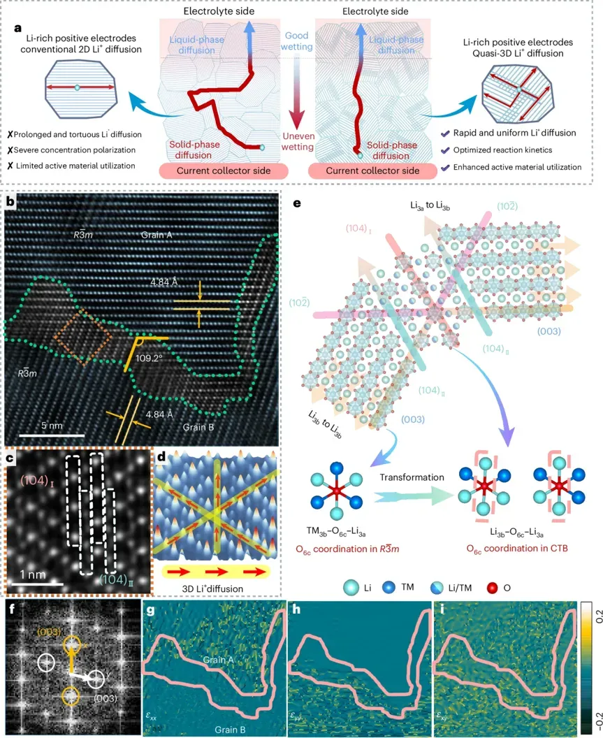
Figure 1. Coherent twin boundary (CTB) microstructure and ion/stress mechanism in CTLRO — HAADF-STEM twin morphology, atomic model, and GPA strain distribution
2. Work Overview: Coherent Twin Boundary Engineering
A team from Xiamen University, in collaboration with multiple institutions, used a precisely staged-temperature calcination process to controllably introduce coherent twin boundaries into a Li-rich layered oxide, producing the CTLRO (coherent-twin-boundary Li-rich layered oxide) material. This approach systematically addresses the three thick-electrode pain points described above. The team combined HAADF-STEM imaging, synchrotron XRD, X-ray absorption spectroscopy (XAS), single-particle mechanical testing, in situ XRD, TOF-SIMS, differential electrochemical mass spectrometry (DEMS), COMSOL simulation, and BatPaC techno-economic modeling to validate the mechanism from multiple, independent angles.
The coherent twin boundaries construct a quasi-three-dimensional lithium-ion diffusion network that substantially increases ion-transport rate compared with the two-dimensional in-layer pathway of conventional LRO. The twin boundaries also disperse concentrated lattice stress across the particle, reducing cyclic deformation. At the interface, oxygen coordination is reconstructed, which activates otherwise electrochemically inactive lattice oxygen to raise reversible capacity while simultaneously stabilizing the oxygen framework and suppressing irreversible oxygen release.
3. Results and Technical Interpretation
3.1 Twin-Boundary Microstructure and Ion/Stress Mechanism (Figure 1)
Figure 1 presents the coherent twin microstructure of CTLRO together with the ion-transport and stress-relief mechanism, including a comparative model of ion diffusion pathways in thick electrodes, HAADF-STEM twin morphology, an atomic-scale crystal model, and geometric phase analysis (GPA) strain mapping. STEM imaging directly resolves the twin (003) crystal plane alongside a periodic Li/transition-metal (TM) mixed (104) plane, explaining the cross-layer Li⁺ transport sites created at the twin interface. The atomic model shows that, within the twin region, the TM3b-O6c-Li3a configuration converts to a Li3b-O6c-Li3a configuration, which activates lattice oxygen. GPA strain analysis confirms that the twin boundaries distribute lattice strain evenly, avoiding the localized high-strain regions that would otherwise cause structural damage.
3.2 Single-Particle Mechanical Testing of PLRO vs. CTLRO (Figure 2)
Figure 2 compares the mechanical, crystallographic, and local atomic-chemistry properties of conventional Li-rich layered oxide (PLRO) and CTLRO, including single-particle compression curves, synchrotron XRD Rietveld refinement, pair distribution function (PDF) analysis, Ni/Co/Mn XAS, wavelet-transform analysis, and EXAFS fitting. The single-particle compression tests demonstrate that CTLRO particles exhibit higher crush strength than PLRO particles, indicating better compatibility with the roll-pressing process used to manufacture thick electrodes at high density. This mechanical comparison — the central data point connecting the coherent-twin-boundary design to practical thick-electrode manufacturing — was measured on the IEST SPFT2000 Single-Particle Mechanical Testing System, which applies controlled compressive load to a single cathode particle and records the force-displacement curve to the point of fracture. Synchrotron XRD data further confirm that the twin boundaries induce moderate lattice expansion, increasing the Li₂MnO₃ unit-cell volume, while PDF and EXAFS results show a shortened Mn–O bond length and a less pronounced distortion of the manganese octahedron in CTLRO relative to PLRO.
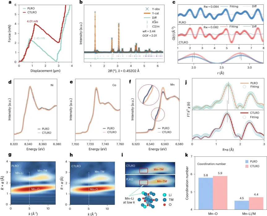
Figure 2. PLRO vs. CTLRO mechanical, crystallographic, and local atomic-chemistry comparison — single-particle compression testing on IEST SPFT2000
3.3 Thick-Electrode Engineering Performance and Techno-Economic Analysis (Figure 3)
Figure 3 focuses on thick-electrode engineering performance and techno-economic analysis, including energy-density modeling of pouch cells at different cathode loadings, cell-manufacturing cost analysis using BatPaC software, high-loading coin-cell cycling, long-term cycling of a 1.05 Ah pouch cell, cross-sectional elemental mapping of the ultra-high-loading electrode, and a single-layer 47.9 mg·cm⁻² lithium-metal pouch-cell test. The modeling shows that raising cathode areal loading reduces the number of stacked layers required per cell, lowering the consumption of current collectors, separators, and other auxiliary materials and reducing manufacturing cost. Cross-sectional SEM and EDS mapping confirm that the high-loading, roll-pressed electrode shows no delamination and uniform distribution of metal elements throughout its thickness.
Electrochemical testing shows that CTLRO enables fabrication of an ultra-high-loading thick cathode up to 47.9 mg·cm⁻², corresponding to an areal capacity of 13.0 mAh·cm⁻², with stable operation across a -15 °C to 55 °C temperature range. At 33.6 and 47.9 mg·cm⁻² loadings, ampere-hour-class pouch cells assembled with CTLRO confirm that the modification strategy is compatible with industrial-scale cell manufacturing. A 1.05 Ah Si/C‖CTLRO pouch cell reaches a cell-level specific energy of 326.7 Wh·kg⁻¹, retaining 88.5% of its capacity and 96.9% of its average voltage after 100 cycles at 30 °C and 100 mA·g⁻¹ — direct evidence of Li-rich cathode cycling stability at high loading. The full modification process requires only calcination-parameter control, with no additional fabrication equipment, and the high-compaction electrode maintains 29% porosity, consistent with industrial standards for thick cathode manufacturing for industrial scale-up.
| Test Condition | Cell Configuration | Key Metric | Result |
|---|---|---|---|
| Coin cell, 30 °C, 83.3 mA·g-1 | Li||CTLRO, 35.6 mg·cm-2, 9.9 mAh·cm-2 | Initial specific discharge capacity | 277.8 mAh·g-1 (vs. 194.3 mAh·g-1 for Li||PLRO) |
| Pouch cell, 30 °C, 100 mA·g-1, 100 cycles | Si/C||CTLRO, 33.6 mg·cm-2, 1.05 Ah | Capacity / voltage retention | 88.5% capacity, 96.9% average voltage retention |
| Pouch cell, 30 °C, 25 mA·g-1, 40 cycles | Li||CTLRO, 47.9 mg·cm-2, 13.0 mAh·cm-2 | Capacity / voltage retention | 250.2 mAh·g-1, 92.1% capacity, 95.7% average voltage retention |
| BatPaC cell-cost modeling | Li||LRO cells, N/P ratio 0.77 | Cost per kWh at increasing loading | Reduced from $127.2 to $100.0/kWh as loading rises from 15 to ~48 mg·cm-2 |
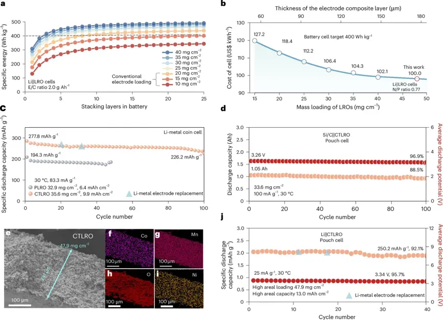
Figure 3. Thick-electrode engineering performance and techno-economic analysis — energy density, manufacturing cost, and 47.9 mg/cm² ultra-high-loading electrode validation
3.4 Multi-Technique Mechanistic Validation (Figure 4)
Figure 4 presents multi-technique coupled mechanistic validation, covering first-cycle charge-discharge curves, a lattice-stress schematic, TOF-SIMS lithium-distribution mapping, in situ XRD, Raman spectroscopy, in situ DEMS oxygen detection, and EIS-DRT (distribution of relaxation times) impedance analysis. TOF-SIMS mapping directly demonstrates that lithium distribution across the CTLRO thick electrode is uniform, eliminating the concentration-polarization gradient seen in conventional thick LRO electrodes. In situ XRD shows that the layered framework of CTLRO is better preserved after cycling, and Raman spectroscopy confirms a significant reduction in lattice strain. DEMS quantitatively measures an order-of-magnitude reduction in oxygen release from the CTLRO cell compared with the PLRO baseline. EIS-DRT analysis shows that impedance at the cathode–solid electrolyte interface shows almost no growth over cycling, substantially mitigating electrolyte side reactions and completing the mechanistic picture of long-term twin-boundary stability.
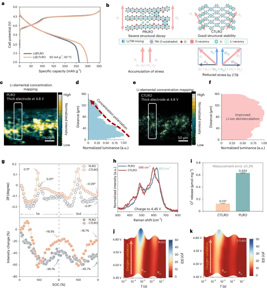
Figure 4. Multi-technique mechanistic validation — TOF-SIMS lithium distribution, in situ XRD/Raman, and DEMS oxygen-release quantification in CTLRO thick electrodes
3.5 PLRO vs. CTLRO: Structural and Performance Comparison
| Property | Conventional PLRO Thick Electrode | CTLRO Thick Electrode | Implication for Thick-Electrode Design |
|---|---|---|---|
| Lithium-ion transport pathway | Two-dimensional in-layer channel only | Quasi-3D pathway via coherent twin boundaries | Reduces concentration polarization at high areal loading |
| Single-particle crush strength | Lower (measured by IEST SPFT2000) | Higher (measured by IEST SPFT2000) | Better tolerance to calendering pressure during thick-electrode roll-pressing |
| Lattice-strain distribution | Concentrated, localized high strain | Evenly distributed via twin boundaries (GPA-confirmed) | Lower incidence of particle cracking over cycling |
| Lattice-oxygen behavior | Continuous, largely irreversible oxygen release | Order-of-magnitude lower oxygen release (DEMS-confirmed) | Reduced cathode-anode cross-talk side reactions, longer cell life |
| Maximum demonstrated areal loading | Limited by ion transport and cracking | 47.9 mg·cm-2 (13.0 mAh·cm-2 areal capacity) | Supports higher cell-level energy density with fewer stacked layers |
| Electrode porosity at high compaction | Variable, often below industrial target | 29%, within industrial standard range | Compatible with existing roll-to-roll manufacturing lines |
How Single-Particle Mechanical Testing Supports Thick-Electrode Development
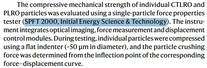
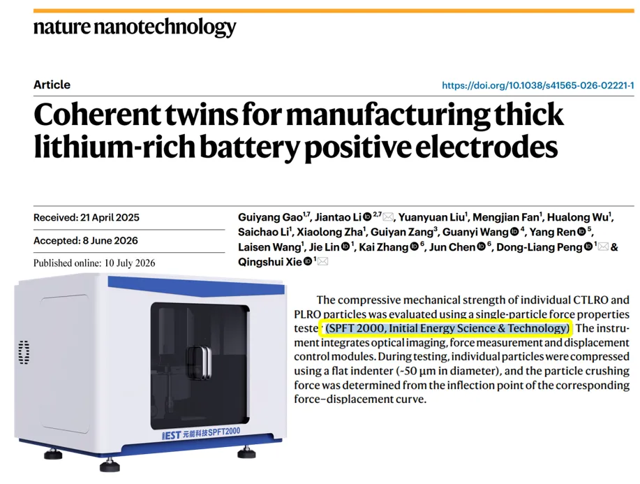
Figure 5. Citation of IEST SPFT 2000 in Nature Nanotechnology for Single-Particle Mechanical Strength Testing
4. Summary and Outlook
This work introduces coherent twin boundaries into a Li-rich layered oxide through a simple calcination process, achieving several coupled benefits: the twin interfaces construct a quasi-three-dimensional lithium-ion channel that resolves the ion-transport bottleneck in thick electrodes; they evenly disperse cyclic electrochemical-mechanical stress, suppressing particle pulverization; and they reconstruct the oxygen coordination environment to activate reversible lattice oxygen while substantially reducing oxygen release and cathode-anode cross-talk. CTLRO supports an industrial-grade ultra-high loading of 47.9 mg·cm⁻², with strong electrochemical performance demonstrated across wide-temperature cycling and in an ampere-hour-class pouch cell. The fabrication process is simple, and the resulting electrode porosity meets commercial standards, indicating a low barrier to industrialization.
At present, this work represents laboratory-scale proof of concept (TRL3–TRL4). Scaling to mass production, or extending the approach to other cathode chemistries, will require further engineering work — including continuous large-area electrode coating and stable calcination control at the ton scale — to advance technology readiness to TRL5 and beyond. The coherent-twin-boundary crystal engineering strategy offers a new, feasible pathway for developing next-generation high-energy-density cathodes for power batteries.
Evaluating Cathode Particle Strength?
The IEST SPFT2000 Single-Particle Mechanical Test System measures compressive force-displacement behavior, crush strength, and fracture toughness of individual cathode or anode particles — the same class of measurement referenced for CTLRO vs. PLRO comparison in this Nature Nanotechnology study.
5. FAQs
5.1 What is a coherent twin boundary (CTB) in a Li-rich cathode?
A coherent twin boundary is a low-energy crystallographic interface where two crystal domains share a mirror-symmetric lattice arrangement without dislocations. Coherent twin boundaries for thick Li-rich cathodes create a quasi-3D Li-ion diffusion pathway in the cathode and distribute lattice strain, addressing ion-transport and cracking limitations that otherwise restrict thick-electrode design.
5.2 What is the difference between PLRO and CTLRO?
PLRO is a conventional Li-rich layered oxide with two-dimensional in-layer lithium transport and no engineered twin structure. CTLRO is produced by staged-temperature calcination to introduce coherent twin boundaries, resulting in higher single-particle crush strength, lower lattice strain concentration, and an order-of-magnitude reduction in oxygen release compared with PLRO.
5.3 How is single-particle crushing strength of cathode materials measured, and why does it matter?
Single-particle crushing strength is measured by applying a controlled compressive load to one particle with a flat indenter and recording the force-displacement curve to the point of fracture. Thick, high-loading electrodes are manufactured under substantial roll-pressing force, and particles that crack under this pressure lose electrochemical performance. IEST SPFT2000 testing in this study confirmed that CTLRO withstands higher compressive stress than conventional PLRO.
5.4 What areal loading defines an ultra-high loading cathode for lithium-ion batteries?
In this study, a Li-rich cathode with 47.9 mg/cm² ultra-high loading achieved 13.0 mAh·cm⁻² areal capacity, with stable operation from -15 °C to 55 °C, demonstrating strong low-temperature Li-rich cathode performance. Values in this range indicate an electrode design capable of supporting high cell-level energy density while remaining compatible with industrial roll-pressing.
5.5 What does Li-rich cathode cycling stability at high loading look like in practice?
A 1.05 Ah Si/C‖CTLRO pouch cell built with the ultra-high-loading thick cathode reached 326.7 Wh·kg⁻¹ cell-level specific energy, retaining 88.5% capacity and 96.9% average voltage after 100 cycles at 30 °C and 100 mA·g⁻¹. A separate 47.9 mg·cm⁻² Li‖CTLRO pouch cell retained 92.1% capacity over 40 cycles at 25 mA·g⁻¹.
5.6 How do coherent twin boundaries help in suppressing oxygen release and reducing electrolyte side reactions in Li-rich cathodes?
Coherent twin boundaries reconstruct the local oxygen coordination environment, converting TM3b-O6c-Li3a sites toward Li3b-O6c-Li3a configurations. This activates lattice oxygen for reversible capacity while stabilizing the oxygen framework; in situ DEMS measurements show an order-of-magnitude reduction in oxygen release, and EIS-DRT analysis shows cathode-electrolyte interfacial impedance stays nearly flat over cycling, indicating reduced electrolyte side reactions.
5.7 How do I select single-particle mechanical testing equipment for cathode particle strength evaluation?
Selecting single-particle mechanical testing equipment depends on required load resolution, displacement precision, and particle-size compatibility with the cathode or anode material under evaluation. The IEST SPFT2000 Single-Particle Mechanical Test System addresses these requirements by recording controlled compressive force-displacement curves for individual particles, reporting crush strength and fracture behavior directly relevant to thick-electrode manufacturability.
5.8 Is coherent twin boundary engineering ready for thick cathode manufacturing at industrial scale-up?
The reported work is a laboratory-scale proof of concept (TRL3–TRL4). The calcination-based modification adds no new fabrication equipment and preserves 29% electrode porosity within industrial standards, but scale-up to ton-level powder calcination and continuous large-area electrode coating still requires further process engineering before reaching TRL5 and above
