-
iestinstrument

Abstract
1. The Challenge of Manual Electrode Brittleness Testing in Battery Production Lines
In modern lithium-ion battery electrode manufacturing, the incoming quality control (IQC) of raw foils and the manufacturing quality control (IPQC) of coated webs rely heavily on mechanical screening. For years, production facilities have adhered to a seemingly standardized empirical protocol: manual unidirectional 180° folding, manual cylindrical roller pressing, and human visual examination against an inspection backlight to detect light leakage.
Despite widespread adoption, battery gigafactories experience persistent yield contradictions. Electrode coils certified as compliant by manual visual inspection frequently develop micro-cracks along their edges or suffer catastrophic web fractures during downstream high-tension winding and cylindrical jelly-roll or prismatic cell assembly. These failures result in severe production line stoppages, scrap losses, and internal short-circuit hazards.
This study compares manual inspection with automated visual inspection using bidirectional folding fatigue cycling as the reference standard. By quantifying the error in manual detection, we identify the root causes of inspection failure and demonstrate the quality control value of automated bidirectional folding testing.
Electrode Brittleness is defined as the mechanical susceptibility of a battery electrode composite or metallic current collector to fracture, crack, or delaminate under localized bending stress or tensile elongation. It is quantified by the number of folding cycles the electrode can withstand before light-transmission defects appear.
2. The Systematic Failure Modes of Conventional Manual Inspection
The root cause of winding scrap does not stem from anomalous production variations, but from systemic flaws in manual testing methodologies. The manual 180° folding test introduces severe operator-dependent variables that prevent data reproducibility:
- Inconsistent Compressive Strain: Operators apply variable manual pressure and rolling speeds, causing uncontrolled deformation radiuses (R) along the fold line.
- Unidirectional vs. Bidirectional Fatigue: Manual testing evaluates only a single forward fold, failing to simulate the alternating tension-compression cycles electrodes endure as they navigate tension rollers, dancer arms, and winding mandrels.
- Visual Detection Limits: Human visual resolution cannot reliably resolve pinholes or micro-cracks smaller than 50–100 μm, whereas microscopic fractures as small as 10 μm are sufficient to propagate into edge tears under production web tension.
- Absence of Traceable Metrics: Manual inspection provides binary (pass/fail) subjective notes without recording numerical defect dimensions, crack surface areas, or fatigue endurance cycles.
3. Architecture of Automated Bidirectional Cyclic Folding Metrology: The IEST FZT2000
To address the limitations of human visual judgment, IEST Instrument developed the Battery Electrode Folding and Roll Light Transmission Test System (FZT2000). The instrument mechanizes the entire sequence: precise bidirectional alternating folding, standardized pneumatic roller compaction, automated high-intensity backlight exposure, and synchronized dual-side optical vision detection.

Figure 1. IEST Electrode Folding and Light Transmission test system (FZT2000) appearance, designed for quantitative assessment of electrode coating brittleness and flexibility with 10 μm detection resolution.
4. Operational Workflow Comparison: Manual Inspection vs. IEST FZT2000
The operational sequence of the automated system contrasts sharply with conventional factory floor testing. The FZT-2000 executes a closed-loop reciprocating cycle where mechanical motion and visual data acquisition are tightly synchronized.
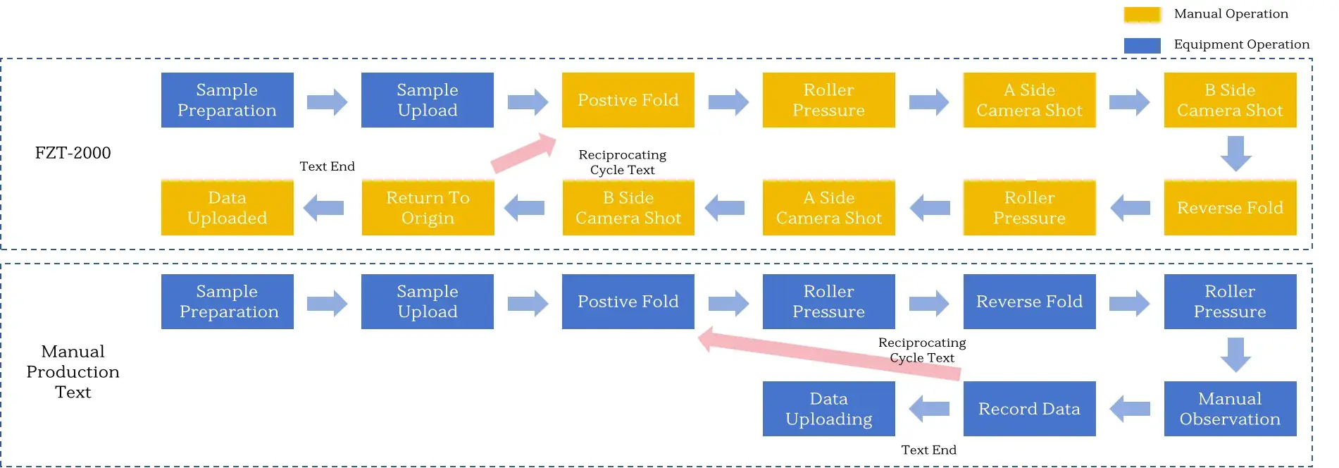
Figure 2. Workflow comparison diagram between the automated IEST FZT2000 Electrode Fold & Roll Light Transmission Tester and conventional manual testing operation.
5. Functional Comparison: Manual vs. IEST FZT2000
Table 1 summarizes the key differences between manual inspection and the IEST FZT-2000 automated system.
| Parameter | IEST FZT2000 | Manual Line Inspection |
|---|---|---|
| Inspection Capabilities | Light pinhole count, size, and area | Light pinhole count only |
| Measurement Accuracy | Dual cameras, 10 μm inspection resolution | Visual inspection, incapable of quantifying defect dimensions |
| Test Duration per Cycle | 30 s | 20 s |
| Image Captures per Cycle | 4 captures | 1 capture |
| Operation Workflow | Manual sampling, automated equipment testing | Manual sampling, manual testing |
| Data Logging & Traceability | Automatic recording and auto-uploading | Manual recording and manual uploading |
6. Controlled Experimental Validation
6.1 Single‑Variable Experimental Design
To evaluate electrode mechanical endurance objectively, application engineers at IEST Instrument established a single-variable experimental matrix. Current collector foils were standardized at fixed industrial gauges:
- Cathode Substrate: Bare aluminum foil with a uniform thickness of 12 μm.
- Anode Substrate: Bare copper foil with a uniform thickness of 9 μm.
Two primary groups were investigated: bare metallic foils without active material layers, and production-grade coated electrodes prepared on the identical substrate lots. To eliminate statistical anomalies and test scatter, 8 parallel specimens ($n = 8$) were tested for each material category under standardized ambient temperature (25 ± 2°C) and relative humidity (45 ± 5%).
6.2 Experimental Data: Cyclic Folding Durability and Optical Light Transmission Metrics
Each specimen underwent cyclic bidirectional folding until light transmission occurred, indicating through-thickness fracture of the metallic current collector. The initial cycle count of light penetration was recorded automatically by the machine vision system. Table 2 presents the average number of folding cycles before first light‑transmission appearance for each group.
| Test Group | Sample Type | Substrate Thickness | Electrode Thickness | Parallel Samples | Avg. Cycles to First Light‑Transmission |
|---|---|---|---|---|---|
| A | Bare Al substrate (uncoated) | 12 μm | — | 8 | 1.1 |
| B | Al-based coated electrode | 12 μm | 177 μm | 8 | 1.9 |
| C | Bare Cu substrate (uncoated) | 9 μm | — | 8 | 3.8 |
| D | Cu-based coated electrode | 9 μm | 150 μm | 8 | 24.6 |
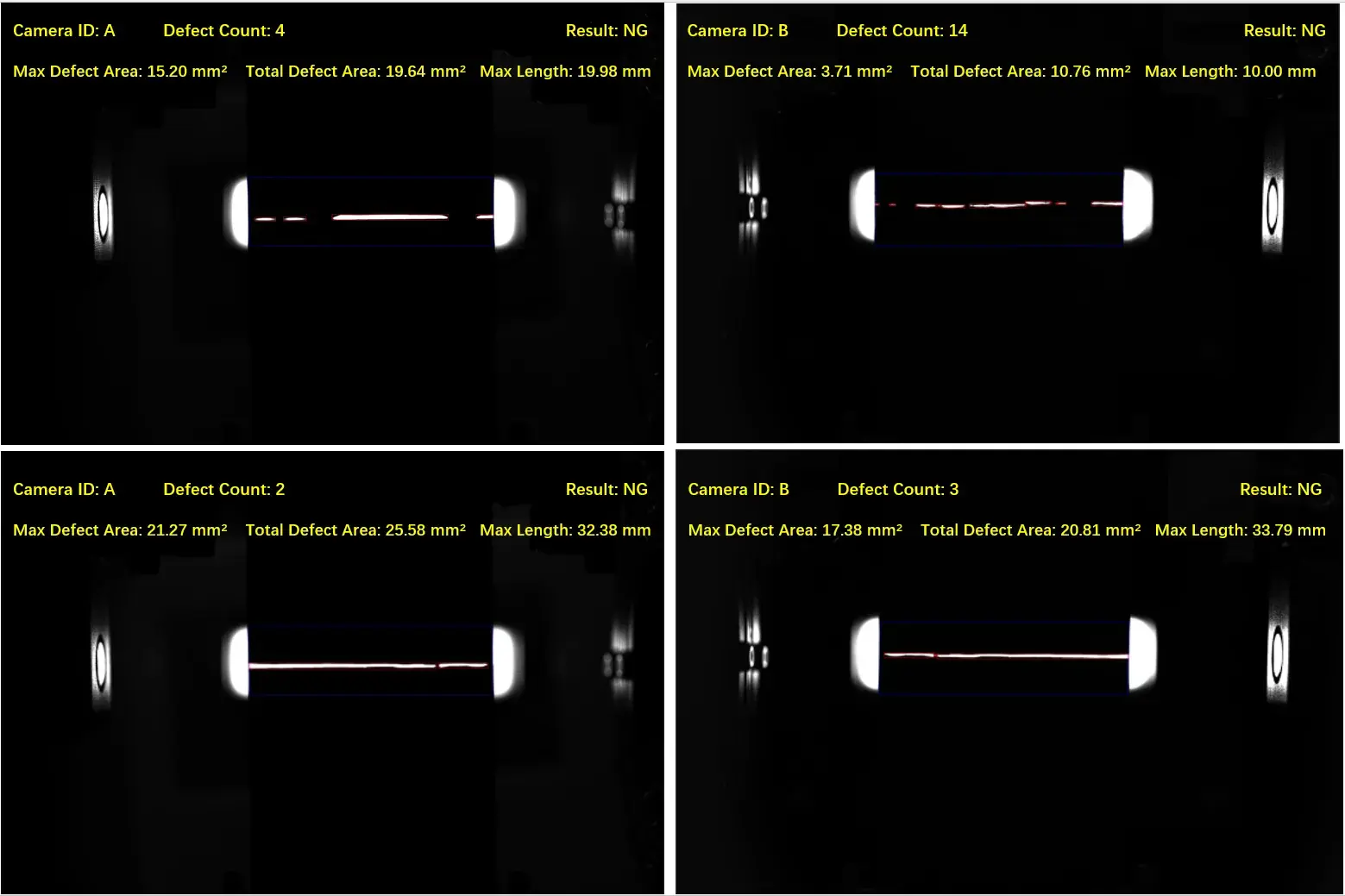
Figure 3. Captured visual defect images from the A and B Sides (front and back) during actual testing.
6.3 Mechanistic Analysis: The Reinforcement Effect of Composite Coatings
The comparative data reveal a clear behavioral pattern across both material systems: under identical substrate thickness, the composite coated electrode demonstrates superior resistance to cyclic folding fatigue compared to bare metal foil.
- 12 μm Aluminum System: The mean endurance cycle count increased from 1.1 cycles on bare foil to 1.9 cycles on the 177 μm cathode coated electrode, representing a 66.7% fatigue life improvement.
- 9 μm Copper System: The mean endurance cycle count rose from 3.8 cycles on bare foil to 24.6 cycles on the 150 μm anode coated electrode, representing a 6.4-fold endurance increase.
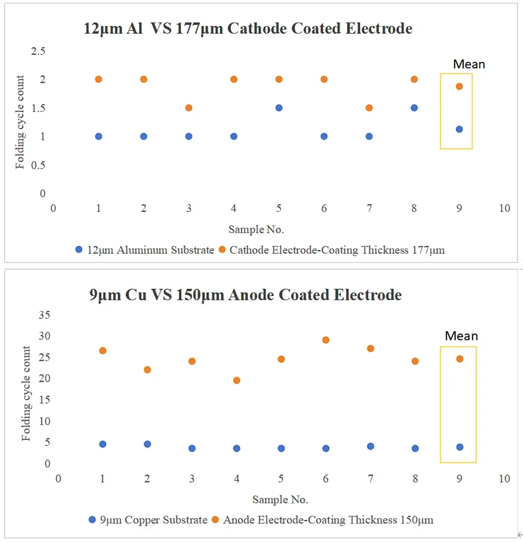
Figure 4. Comparison of light transmittance between substrate foil and coated electrode.
The table and accompanying charts clearly reveal a striking contrast: under identical substrate thickness, the repeated folding resistance of coated composite electrodes comprehensively outperforms that of corresponding bare metal foils; coating reinforcement delivers a step-change boost to the folding endurance of the Cu anode system.
6.4 Data Analysis and Engineering Insights
The results demonstrate that electrode brittleness is significantly reduced by coating application. For both cathode (aluminum) and anode (copper) systems, coated electrodes exhibit superior folding resistance compared to bare substrates. The most dramatic improvement occurs in the copper system, where the coating increases folding cycles from 3.8 to 24.6 — a 6.4‑fold enhancement. This confirms that coating not only provides electrochemical functionality but also mechanically reinforces the electrode substrate.
Practical implications for production:
- Coating adhesion and compaction density are critical parameters that affect electrode flexibility. Optimizing these factors can further improve folding resistance.
- Different threshold standards should be established for cathode and anode electrodes. Aluminum‑based cathodes have lower intrinsic fold resistance; therefore coating quality is the primary control point. Copper‑based anodes show substantial improvement after coating, allowing for incoming material grading based on folding cycle data.
- When winding cracks or breakage occur, the standardized folding test provides a rapid root‑cause analysis: low cycles on bare substrate indicate foil defects; low cycles on coated electrode point to coating or calendering process anomalies.
🔬 Standardize Your Electrode Brittleness Quality Control
The IEST FZT-2000 delivers precise, repeatable electrode folding tests with 10 μm resolution, dual‑camera defect detection, and automated data logging — eliminating human error and providing actionable insights for coating process optimization.
7. Conclusion
This controlled study, performed with the IEST Electrode Folding & Roll Light Transmission Tester (FZT2000), systematically quantifies the reinforcement effect of coating on electrode brittleness. By maintaining constant substrate thickness and using four parallel sample groups, we obtain objective cycle‑life data that clearly demonstrates coating improves folding resistance. Future work will extend this methodology to different coating loadings and compaction densities, building a comprehensive database for front‑end electrode brittleness quality control. Quantitative folding testing replaces traditional manual inspection, enabling precise, data‑driven quality management in lithium‑ion battery production.
8. FAQs
8.1 What is electrode brittleness in lithium-ion battery manufacturing?
Electrode brittleness is the mechanical susceptibility of current collector foils and coated electrode composites to fracture under bending or tensile strain. It directly governs whether an electrode web can withstand winding without suffering edge cracks or breakage.
8.2 What is the difference between manual 180° folding and automated folding fatigue testing?
Manual 180° folding relies on uncontrolled hand pressure, evaluates only a single bending direction, and uses subjective naked-eye inspection. Automated testing with the IEST FZT2000 applies standardized pneumatic roller pressure across bidirectional cyclic folds, capturing micro-fractures down to 10 μm with dual-side telecentric cameras.
8.3 How does electrode coating affect the folding durability of metallic current collectors?
The composite electrode coating reinforces thin metallic foils by redistributing localized bending strain through its polymeric binder network. In experimental tests, coating layers increased the folding fatigue endurance of 12 μm aluminum foil by 66.7% and 9 μm copper foil by 6.4-fold.
8.4 How do battery manufacturers prevent electrode edge cracking during cell winding?
Manufacturers prevent winding cracks by monitoring incoming foil elongation, optimizing binder elasticity, avoiding over-compaction during calendering, and utilizing automated cyclic folding tests to establish clear go/no-go fatigue limits before slitted coils reach winding machinery.
8.5 How to prevent electrode edge cracking during winding?
Edge cracking can be prevented by optimizing coating adhesion and compaction density, ensuring uniform coating thickness, and using quantitative folding tests to screen electrode flexibility before winding. The IEST FZT2000 provides early detection of brittle electrodes.
