

📄 Source Paper
Rui Tang, Yuelei Xu, Jinyang Dong, Qi Shi, Kang Yan, Yibiao Guan, Yun Lu, Yu Su, Jinzhong Liu, Fangze Zhao, Yi Jin, Ning Li, Yuefeng Su, Feng Wu, Lai Chen.
DOI: 10.1016/j.apenergy.2025.126870
| Journal: Applied Energy
| Institutions: Beijing Institute of Technology, Chongqing Innovation Center of Beijing Institute of Technology, China Electric Power Research Institute, IEST Co., Ltd. (Xiamen), Tsinghua University
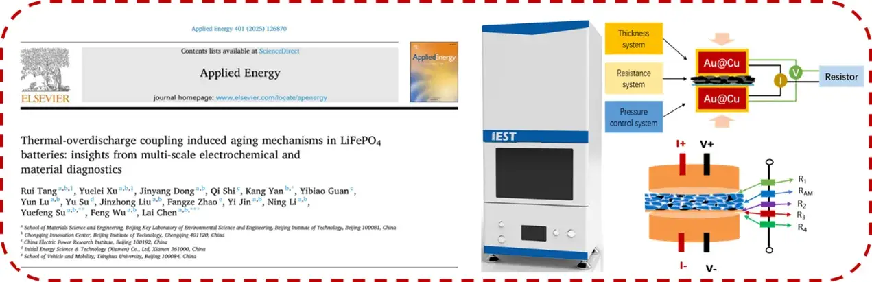
✓ IEST BER2100 Battery Electrode Resistance Tester used in this research
LFP batteries are a cornerstone technology for electric vehicles and energy storage systems, prized for their safety and cost-effectiveness. In real-world applications, however, these batteries are frequently subjected to coupled thermal and electrochemical stresses. The combined effect of elevated temperature and deep overdischarge can significantly accelerate battery aging, leading to rapid capacity fade and impedance growth. While the individual impacts of heat or overdischarge have been studied, the synergistic aging mechanism under their combined stress remains insufficiently understood. A clear analysis of this coupled failure behavior is crucial for enhancing battery longevity and safety.
A research team employed a comprehensive, multi-scale diagnostic strategy to systematically reveal the aging mechanism of LFP batteries under thermal-overdischarge coupling. The study utilized an orthogonal experimental design to evaluate the effects of temperature (25 °C, 45 °C, 65 °C) and discharge cutoff voltage (2.5 V, 1.0 V, 0.5 V). Researchers combined electrochemical techniques like DCIR and EIS with advanced material diagnostics including ultrasonic imaging, SEM/TEM, XRD, and ToF-SIMS.
The orthogonal experimental design quantified a powerful synergistic effect. Battery life acceleration factors reached 7.33× under 45 °C/0.5 V conditions and 8.80× under 65 °C/0.5 V, far exceeding the impact of either stressor alone.
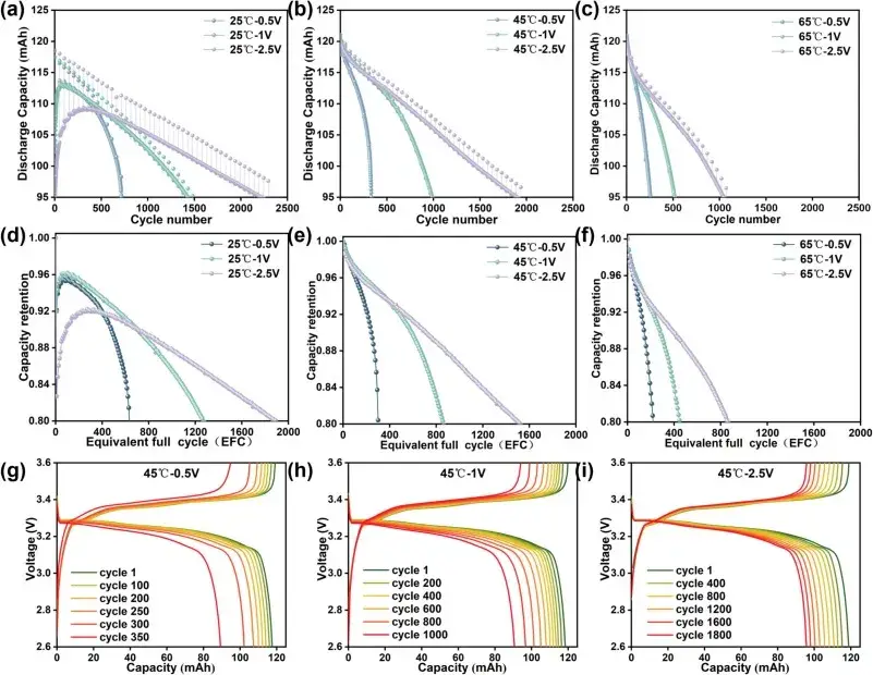
Figure 1. Validation of the accelerated aging effect under coupled stress of high temperature and deep overdischarge
Aging consistently exhibited three distinct stages: activation, linear decay, and accelerated decay. Increasing temperature and discharge depth shortened the linear stage and brought forward the accelerated decay phase, accompanied by significantly increased polarization.
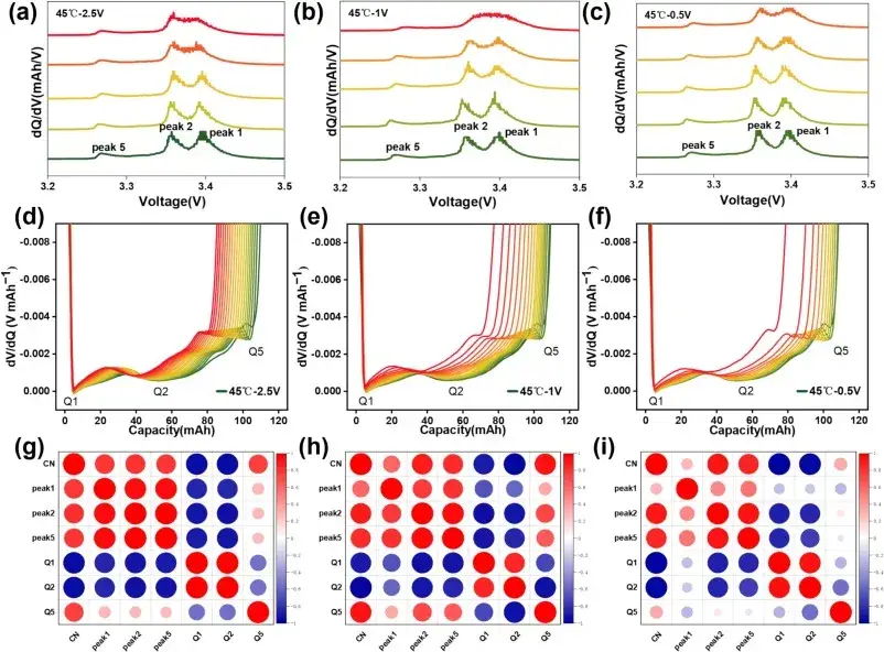
Figure 2. IC/DV curves under different coupled stress conditions and correlation analysis of stress factors.
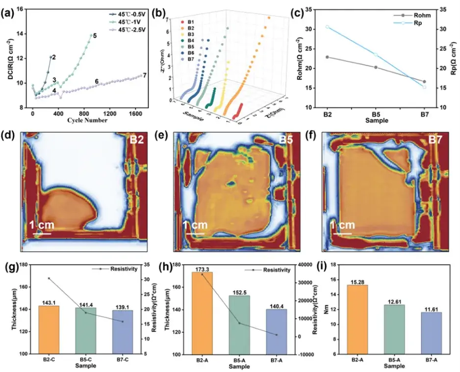
The evolution of DCIR provided a clear, non-destructive marker for failure-stage transition. Under moderate 2.5 V discharge, DCIR increased linearly. At a deep discharge of 1.0 V, its growth shifted from linear to exponential. At the extreme 0.5 V cutoff, DCIR exhibited exponential growth from the beginning. This inflection point reliably indicates the onset of synergistic failure mechanisms like SEI breakdown, dead-lithium accumulation, and metal deposition. The DCIR curves and associated impedance, electrolyte wetting, electrode thickness, and resistance measurements shown in Figure 3 were obtained using the IEST BER2100 Battery Electrode Resistance Tester, which measures through-thickness electrode resistance directly on practical electrode samples.
| Discharge Cutoff Voltage | DCIR Growth Pattern | Aging Stage Transition | Implication for LFP Battery Aging Mechanism |
|---|---|---|---|
| 2.5 V (moderate) | Linear increase | Extended linear-decay stage | Baseline aging rate; failure mechanisms remain independent rather than synergistic |
| 1.0 V (deep) | Shifts from linear to exponential | Accelerated-decay stage brought forward | Marks the DCIR inflection point — onset of cooperative failure mechanisms |
| 0.5 V (extreme, 65 °C) | Exponential from the beginning | Accelerated decay dominates almost immediately | Triggers non-typical failure modes: FePO4 phase separation, copper migration |
Combining microscopy and spectroscopy uncovers mechanistic details:
Graphite anode: deep overdischarge causes graphite structural collapse and pronounced SEI thickening. ToF-SIMS and TEM show concentrated Li- and SEI-rich layers; μXRF and μ-probe mapping reveal copper enrichment consistent with current collector dissolution and migration.
Copper current collector: under severe deep-discharge and high temperature, Cu dissolves and migrates across the cell, eventually depositing on the cathode surface—further disrupting electrode function.
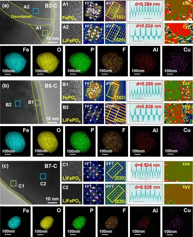
LFP cathode: at extreme coupling (65 °C / 0.5 V) evidence of FePO₄ phase separation and lattice damage appears, indicating cathode structural degradation beyond typical cycling effects.
Macroscopic: ultrasonic imaging verified gas generation and electrode delamination in heavily stressed cells.
These observations show that thermal and overdischarge stresses synergistically destabilize both electrodes and the cell’s internal chemistry, generating unique failure pathways that accelerate DCIR and capacity loss.
From an engineering viewpoint the study suggests several actionable points:
Use DCIR inflection detection as a field-deployable, nondestructive early-warning metric to trigger protective actions or further inspection.
Design accelerated aging tests that combine thermal and electrical stressors realistically, rather than treating them independently, to obtain valid lifetime projections. The orthogonal design framework provides an efficient blueprint.
Mitigate deep overdischarge risk through BMS policies, especially in systems that may experience elevated ambient temperatures.
Consider materials and manufacturing countermeasures (improved SEI stabilizers, copper corrosion inhibitors/coatings, and cathode microstructure optimization) to resist coupled stress.
Measuring DCIR and Electrode Resistance for LFP Aging Studies
The IEST BER2100 Battery Electrode Resistance Tester measures through-thickness electrode resistance — coating, contact, and current-collector resistance — the same class of data referenced for DCIR inflection-point analysis in this Applied Energy study.
This comprehensive multi-scale study demonstrates that thermal and overdischarge stresses act synergistically to accelerate aging in LFP batteries and can trigger atypical failure modes (copper dissolution, FePO₄ phase separation) under extreme coupling. The identification of a DCIR inflection point as a nondestructive marker of failure-mode transition is a particularly practical outcome. These insights should inform more realistic accelerated test protocols, BMS safeguards and materials design choices for safer, longer-lived LFP batteries systems.
IEST Battery Electrode Sheet Resistance Tester(BER2500)
The BER2100 is a multifunctional electrode resistance analyzer that combines a high-precision pressure control system with integrated electrode thickness measurement and resistance analysis. Using the double-sided controllable-pressure disc electrode method, the BER2100 directly measures the total through-thickness resistance of practical electrode samples, resolving coating resistance, coating–current-collector contact resistance, and current-collector resistance as separate components. In this study, this capability provided the resistance data underlying the DCIR inflection-point analysis, and more broadly the BER2100 is applicable to electrode formulation development and process-stability monitoring.
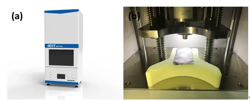
Figure 5. IEST battery electrode resistance tester (BER series) — appearance and structural diagram
Under combined high-temperature and deep-overdischarge stress, LFP batteries age through three stages — activation, linear decay, and accelerated decay — with DCIR growth shifting from linear to exponential at a specific inflection point that marks the onset of synergistic failure mechanisms including SEI breakdown, dead-lithium accumulation, and copper dissolution/deposition.
A DCIR inflection point is the moment DC internal resistance growth shifts from a linear to an exponential rate during cycling. It is a non-destructive, field-deployable indicator that the cell has entered a stage of cooperative failure mechanisms rather than simple, independent degradation, making it useful for early-warning monitoring.
In this study, life acceleration factors reached 7.33× at 45 °C with a 0.5 V discharge cutoff and 8.80× at 65 °C with a 0.5 V cutoff, compared with baseline conditions — far exceeding the effect of elevated temperature or deep overdischarge alone.
FePO₄ phase separation is a non-typical cathode degradation mode in which the LFP crystal structure separates into distinct phases with lattice damage. In this study, it was observed only under extreme coupled stress (65 °C combined with a 0.5 V discharge cutoff), beyond the effects seen in typical cycling.
Under severe deep-discharge combined with high temperature, the anode potential can rise enough to dissolve the copper current collector. The dissolved copper then migrates across the cell and deposits on the cathode surface, further disrupting electrode function and accelerating capacity fade.
DCIR is measured by applying a direct-current pulse load and recording the resulting voltage drop, typically alongside through-thickness electrode resistance measurements that separate coating, contact, and current-collector contributions. In this study, the underlying resistance data were measured using the IEST BER2100 Battery Electrode Resistance Tester.
