-
iestinstrument

Abstract
1. Introduction: The Critical Role of Powder Compaction Density
Powder compaction density is a pivotal metric in lithium-ion battery design, directly linked to critical performance parameters including capacity, internal resistance, and cycle life (Figure 1). Battery electrode materials characterization encompasses two related but distinct measurements: the compaction density of the finished electrode sheet (measured after slurry preparation, coating, roll pressing, baking, weighing, and thickness measurement), and the compaction density of the raw cathode or anode powder (measured directly on loose powder under controlled uniaxial pressure).
The traditional electrode-sheet evaluation approach has a long testing cycle, low throughput, and the electrode manufacturing steps introduce hazards to personnel and the environment. A more efficient and direct approach measures the powder compaction density (sometimes called press density) of raw cathode and anode materials using a fixed-diameter die and a precision press, with high-accuracy in-situ thickness measurement enabling rapid compaction density calculation. As this metric becomes a standard acceptance criterion for material suppliers and battery manufacturers, ensuring consistent and comparable test results across laboratories is essential.
This study investigates a key but frequently overlooked variable: how the pressure application method during testing influences measured powder compaction density, and what that means for comparing data between laboratories or instruments.
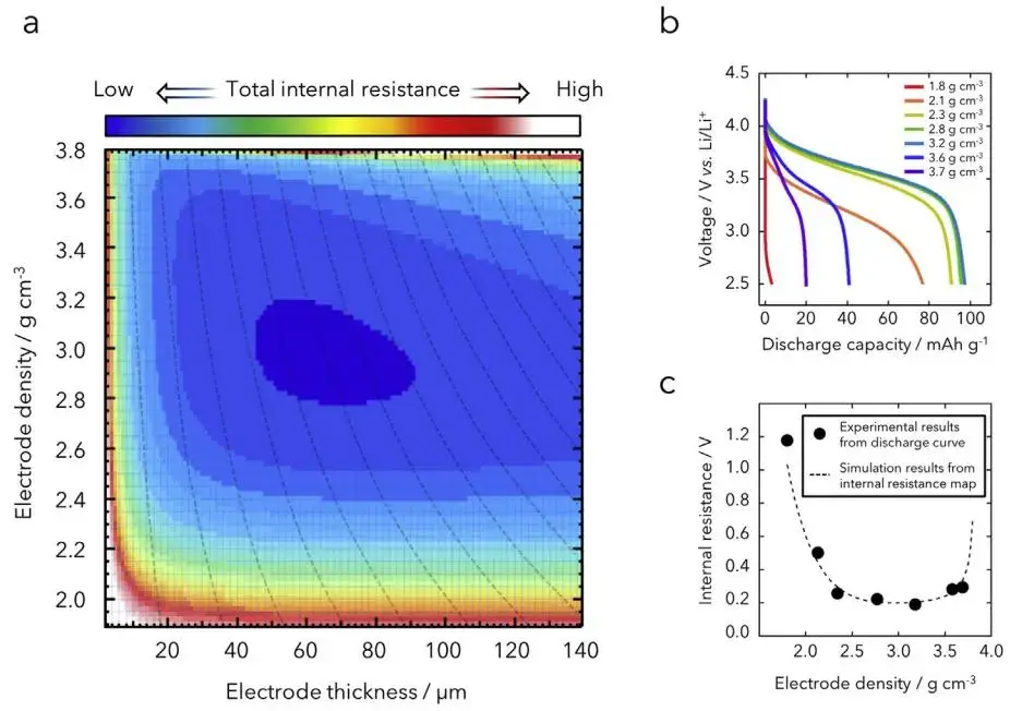
Figure 1. Relationship between electrode compaction density and battery internal resistance and capacity — compaction density directly determines both cell energy and rate capability
2. Test Methods and Parameters
2.1 Test Materials and Modes
Three representative battery electrode materials were selected:
- NCM (lithium nickel cobalt manganese oxide) cathode
- LFP (lithium iron phosphate) cathode
- Graphite anode
Each material was tested using three distinct pressure application modes:
-
Single-point test: Direct compression to target pressures of 50, 100, 150, and 200 MPa, with a 10-second hold at each target pressure. Measures compaction density at a single discrete pressure point without prior loading history.
-
Stepwise pressure test (variable pressure): Gradual compression from 10 to 200 MPa in 10 MPa increments, with a 10-second hold at each step. Provides continuous compaction density versus pressure profile; accumulates loading history progressively.
-
Unloading pressure test (step-release): Same stepwise loading protocol, but after each pressure step the load is released to 3 MPa for a 10-second hold before proceeding to the next step. Measures compaction density in the partially-unloaded state, quantifying elastic springback (rebound).
2.2 Instrumentation: PRCD3100 Battery Powder Compaction Density Tester
All tests were conducted using the IEST PRCD3100 Powder Compaction Density & Resistivity Tester (Figure 2). This system provides controlled, programmable pressure application and high-precision in-situ thickness measurement, both essential for accurate powder compaction density calculation across the full 10–200 MPa range. The PRCD3100 supports all three test modes described above as switchable software settings, enabling direct comparison without changing hardware or die geometry between tests.
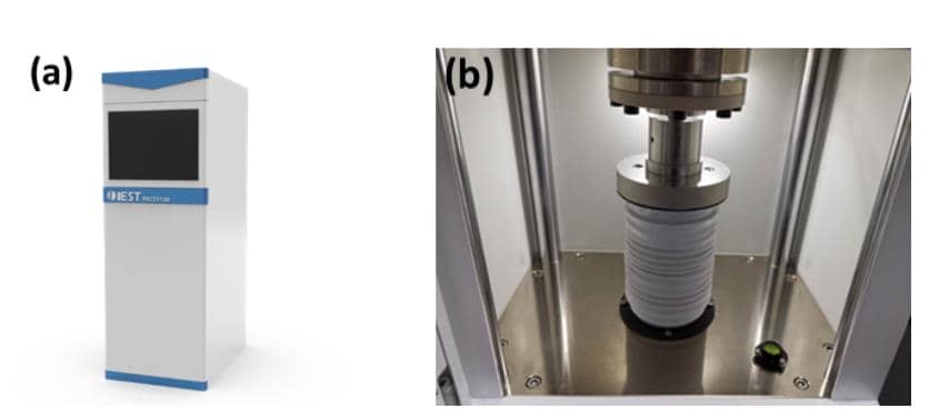
Figure 2. IEST PRCD3100 Powder Compaction Density & Resistivity Tester — (a) appearance; (b) structural diagram; battery powder compaction tooling supporting single-point, stepwise, and unloading pressure test modes up to 200 MPa
3. Analysis of Results
3.1 Visualizing the Pressure-Time Profile
The fundamental difference between the three test modes is their pressure-time history. Figure 3 shows schematic pressure profiles for each method at a 200 MPa target. The single-point mode applies pressure abruptly to the target; the stepwise mode ramps incrementally; the unloading mode adds a controlled release phase between each step. These distinct loading histories directly affect how particles rearrange, deform, and pack — producing different final compaction density values even at the same target pressure.
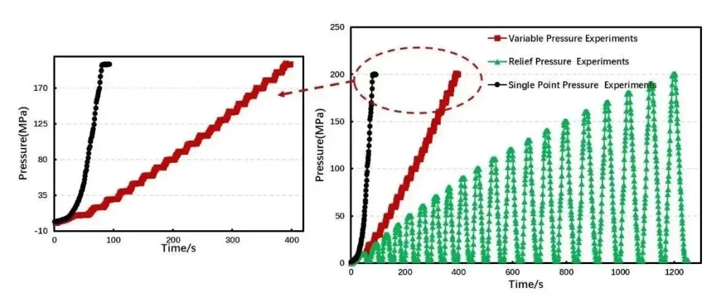
Figure 3. Pressure-time profiles for three powder compaction density test methods at 200 MPa target — single-point (left), stepwise (center), and unloading step-release (right)
3.2 Comparative Compaction Density Results Across Materials
Figure 4 shows measured powder compaction density (press density) for NCM, LFP, and graphite at 50, 100, 150, and 200 MPa using all three methods. Significant differences between methods emerged for all three materials.
The physical mechanisms behind these differences arise from the complex multi-stage nature of powder compression:[2]
- Low pressure — particle rearrangement: Particles slide and reorient to fill inter-particle voids, forming a denser packing state. Porosity decreases.
- Intermediate pressure — elastic deformation: Particles deform reversibly. Inter-particle porosity changes less, but pore diameter decreases.
- High pressure — plastic deformation and fracture: Irreversible particle deformation and, for brittle materials such as LFP, particle fracture further reduce pore diameter.
Single-point vs stepwise comparison: At low pressure the two methods agree well; differences grow with increasing pressure because the stepwise method applies the same loading history multiple times at intermediate pressures, progressively reorienting particles (analogous to a multi-pass calendering process). This is consistent with Samsung’s research demonstrating that a two-step roll-pressing process — where a first soft pass reorients graphite particles perpendicular to the pressing direction, reducing stress and promoting uniform pore distribution, before a second pass achieves target density — produces electrodes with significantly reduced springback and swelling.[3] The stepwise compaction density test is therefore the closest powder-level analog to industrial multi-step calendering.
Unloading test comparison: Compaction density measured in the unloading mode is consistently lower than the other two methods. This is because the step-release protocol captures the partially recovered state: when large load is removed to a small residual load (3 MPa), the elastic deformation component recovers elastically, increasing the measured compact thickness and thus reducing the calculated compaction density. This makes the unloading test the appropriate choice for quantifying elastic springback and distinguishing elastic from plastic deformation components — rather than for absolute compaction density benchmarking.
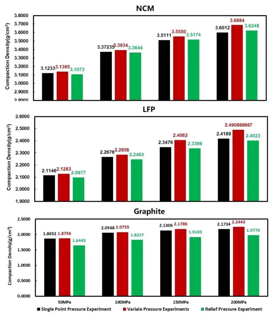
Figure 4. Powder compaction density (press density) results for NCM, LFP, and graphite at 50–200 MPa — all three pressure methods produce measurably different values at each pressure point; stepwise method recommended for electrode calendering correlation
These findings underscore a critical point for laboratory benchmarking: comparing powder compaction density data is only valid if the pressure application method is identical. Ignoring this variable can lead to incorrect material rankings and wasted R&D effort when data from different instruments or protocols are compared.
4. Linking Powder Compaction Density to Calendering Models and Process Parameters
Powder compaction density data from the stepwise test can be used directly to build predictive models for electrode roll-pressing. Researchers at TU Braunschweig modeled the calendering process and derived a relationship between coating density ρc and compaction load qL:[5]
\(\rho_c = \rho_{c,\max} – (\rho_{c,\max} – \rho_{c,0}) \exp\left(-\frac{q_L}{\gamma_c}\right)\)
Among them, \(\rho_{c,\max}\) and \(\gamma_c\) can be obtained by fitting experimental data, which represent the maximum compaction density that the coating can achieve and the coating compaction impedance, respectively. These fitting parameters can be obtained by powder compaction experiments, for example, the maximum compaction density \(\rho_{c,\max}\) that can be achieved by the coating is the limit value of the powder materials compaction density that basically no longer increases in the variable pressure test experiment. The compaction impedance \(\gamma_c\) can also be obtained by fitting the formula to the results of powder compaction density under a series of different pressures. In this way, for a specific powder, the compaction density process model can be obtained to know the electrode roll pressure experiment.
5. Conclusion: Standardizing Powder Compaction Density Measurement
As powder compaction density and press density become universal benchmarks for cathode and anode material qualification, standardizing the test protocol is essential. This study demonstrates that the pressure application method is a major source of measurement variation, affecting results through particle rearrangement, elastic and plastic deformation, and springback — mechanisms whose relative contributions differ between single-point, stepwise, and unloading test modes.
For most electrode material qualification and inter-laboratory comparison applications, the stepwise pressure test is recommended: it provides the full compaction density versus pressure profile in a single run, most closely simulates multi-pass industrial calendering, and produces consistent results for both cathode materials (NCM, LFP) and anode materials (graphite). The unloading test complements this by quantifying elastic recovery, which is directly relevant for predicting electrode springback during and after calendering.
6. References
[1] B K K A, A S A, A H N, et al. Internal resistance mapping preparation to optimize electrode thickness and density using symmetric cell for high-performance lithium-ion batteries and capacitors. Journal of Power Sources, 2018, 396: 207–212.
[2] Yang Shaobin, Liang Zheng. Lithium-ion Battery Manufacturing Process Principles and Applications.
[3] Improved swelling behavior of Li ion batteries by microstructural engineering of anode. Journal of Industrial and Engineering Chemistry, 2019, 71: 270–276.
[4] Liang Huamei, Zeng Yong, Huang Shijian, et al. Study on the Conditions of Compaction Density Test for Positive Electrode Material of Lithium Battery. Guangdong Chemical Industry, 2021, 48(19): 3.
[5] Meyer C, Bockholt H, Haselrieder W, et al. Characterization of the Calendering Process for Compaction of Electrodes for Lithium-Ion Batteries. Journal of Materials Processing Technology, 2017.
7. FAQs
7.1 What is compaction density in battery electrode materials, and how is it measured?
Compaction density (also called press density in some measurement contexts) is the bulk density of a battery electrode powder compact formed by applying controlled uniaxial pressure — calculated as the mass of powder divided by the volume of the compact at a defined pressure point. It is measured using a powder compaction density tester such as the IEST PRCD3100, which applies a defined pressure profile to a powder sample in a fixed-diameter die while recording thickness with high precision, enabling automatic compaction density calculation. For battery cathode and anode materials, typical measurement pressures range from 10 to 200 MPa. Compaction density is a key specification for material quality control because it predicts achievable electrode density after industrial calendering, which in turn determines cell volumetric energy density and internal resistance. Because different pressure application methods produce different results, this study recommends the stepwise method (10–200 MPa in 10 MPa steps) as the most reproducible and industrially relevant protocol for NCM, LFP, and graphite materials.
7.2 What is the difference between press density and compaction density?
Press density and compaction density refer to the same measurement: the bulk density of a powder compact formed by pressing under a defined load. The term “press density” is commonly used in materials science and powder technology contexts to describe the density immediately after pressing (under load or after springback, depending on the protocol). “Compaction density” is the preferred term in battery electrode materials characterization. In battery manufacturing quality control, the term compaction density specifically refers to this press density measured at a standardized pressure point (typically 3 tons or a defined MPa value for a fixed die diameter), and it is used as an acceptance criterion for incoming cathode and anode powders from material suppliers. The numerical value of compaction density or press density reported for any material must always be accompanied by the measurement pressure and protocol, because as this study demonstrates, different pressure methods produce different values even at the same nominal pressure target.
7.3 Why does the pressure application method change the measured powder compaction density?
Powder compression is a multi-stage process involving distinct deformation mechanisms that are sensitive to loading history. At low pressure, particles rearrange and slide into denser packing. At intermediate pressure, elastic deformation reduces pore diameter without permanent change. At high pressure, irreversible plastic deformation and, for brittle materials, fracture further densify the compact. A single-point test (jumping directly to target pressure) does not give particles time to progressively rearrange at intermediate loads, producing a different final packing state than a stepwise test that applies incremental loads. The unloading test captures a partially springback state after releasing load, recording lower density because the elastic deformation component has partially recovered. These are not artifacts or errors — they are physically real differences in how the powder responds to different mechanical histories, and they mean that compaction density data is only comparable when the pressure application protocol is identical between measurements.
7.4 How does powder compaction density relate to electrode calendering in battery manufacturing?
Electrode calendering — passing a coated electrode sheet between precision rollers under controlled pressure — is the direct industrial equivalent of powder compaction density testing. The stepwise compaction density test mirrors multi-step industrial calendering: progressive pressure application allows particle rearrangement at each step, just as multi-pass calendering progressively densifies the electrode coating. The compaction density vs pressure profile from the stepwise test (generated by the PRCD3100) can be used to extract two key parameters for electrode calendering process models: ρc,max (the maximum achievable coating density — the plateau value in the stepwise curve) and γc (compaction impedance — fitted from the stepwise data). These parameters allow engineers to predict final electrode density at any calendering load, without running physical roll-pressing experiments for every candidate formulation.
7.5 What battery powder compaction tooling is available for measuring compaction density?
The primary battery powder compaction tooling for compaction density measurement consists of a precision powder compaction press integrated with a high-accuracy in-situ thickness sensor, a fixed-diameter die (defining the measurement area), and analysis software that calculates compaction density automatically from mass, thickness, and die dimensions. The IEST PRCD3100 Powder Compaction Density & Resistivity Tester is a dedicated instrument of this type, supporting all three pressure application modes (single-point, stepwise, and unloading) in a single platform through software selection — eliminating the need to change hardware between protocols. It covers pressures up to 200 MPa and simultaneously measures powder resistivity and conductivity in addition to compaction density, making it a multi-parameter characterization tool for cathode materials (NCM, LFP, LCO, LMFP), anode materials (graphite, silicon-carbon, hard carbon), and conductive additives.
