-
iestinstrument

Abstract
📄 Source Paper
Kun Qin, Liangdong Lin, Kai Jiang, Hailong Yu, Tingting Xu, Chunxi Tian, Binghang Liu, Cheng Tan, Mai Gao, Liumin Suo
Breaking Energy Density-Stress Trade-Off in Anode-Free Lithium Pouch Cells
| DOI: doi.org/10.1002/adma.73652
| Journal: Advanced Materials
| Institutions: Chinese Academy of Sciences (Beijing National Laboratory for Condensed Matter Physics)
✓ IEST In-Situ Cell Swelling Testing System(SWE2110) & IEST Battery Electrode Resistance Tester(BER2500) used in this research
1. Why Anode-Free Lithium Metal Battery Swell
In an anode-free lithium metal battery, no metallic lithium is pre-placed on the negative electrode; lithium ions deposit directly onto the copper current collector during charging. This construction can readily achieve mass energy densities above 400 Wh/kg and volumetric energy densities above 1000 Wh/L. However, lithium deposition tends to form loose, moss-like, or even dendritic structures. Repeated deposition and stripping, particle pulverization, and reconstruction of the solid electrolyte interphase (SEI) cause the cell to continuously expand. When the cell is constrained by a module or a rigid outer casing and cannot freely swell, that deformation does not disappear — it converts into internal stress within the cell.
Anode-Free Lithium Metal Battery (AF-LMB) refers to / is defined as a lithium battery architecture in which no metallic lithium is pre-loaded onto the negative electrode; lithium is instead electroplated onto a bare current collector (typically copper) during the first charge, enabling higher energy density than conventional graphite-anode lithium-ion batteries at the cost of larger volume swelling during cycling.
2. Quantifying the Trade-Off: Stress Accumulates as Stacks Increase
The study compared swelling behavior among conventional lithium-ion batteries (LIB), anode-free lithium metal battery (AF-LMB), and lithium metal batteries (LMB) with a pre-placed lithium anode. Under zero mechanical restraint, cell swelling ratios reached 6% for LIB, 33% for AF-LMB, and 74% for LMB. Under the constant-thickness mode (CTM) used to simulate a rigid, constant-thickness battery case, the stack-on-stack stress effect became more pronounced as the number of stacked cell layers increased: peak pressure for 2-, 6-, and 12-layer anode-free cells reached approximately 1 MPa, 2.5 MPa, and 5 MPa respectively, with the 12-layer cell accumulating roughly 3.76 times the pressure of the 2-layer cell and approximately 6 times the stress level of a conventional graphite-anode lithium-ion cell. Under this compression, cell porosity loss reached as much as 20%, well above the roughly 3% typically seen in conventional lithium-ion cells. Rising pressure compresses the separator’s pore structure, increases polarization, and, in severe cases, can close the separator or allow lithium dendrites to pierce it, causing cell failure. Earlier industry approaches attempted to use porous scaffolds to accommodate lithium deposition, but the added thickness and weight of these porous layers directly eroded the energy-density advantage of the anode-free design, creating a persistent performance trade-off.
Constant-Thickness Mode (CTM) refers to / is defined as a test protocol that mechanically holds a pouch cell at a fixed thickness during cycling, simulating a rigid battery case or module constraint; under CTM, deformation that would otherwise appear as free swelling is instead measured as internal pressure.
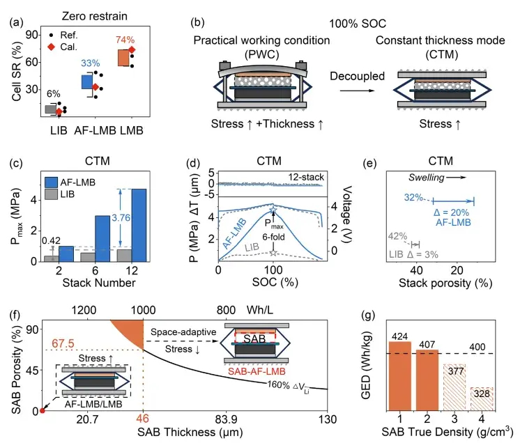
Figure 1. Comparison of swelling ratio and peak restraint pressure across 2, 6, and 12-layer stacks for LIB and anode-free lithium metal battery pouch cells
3. Design Criteria for the Space-Adaptive Buffer (SAB)
To resolve this trade-off, the research team developed a space-adaptive buffer (SAB) and established quantitative material design criteria centered on the buffer layer’s porosity, thickness, and true density. The engineering boundaries were defined explicitly: cell gravimetric energy density greater than 400 Wh/kg, volumetric energy density greater than 1000 Wh/L, stress controlled within 2 MPa, an expansion rate close to that of commercial lithium-ion batteries, and deposition space reserved for up to 160% of the theoretical dense lithium volume.
Space-Adaptive Buffer (SAB) refers to / is defined as an engineered porous layer placed at the anode-free current collector, designed by quantitative criteria on porosity, thickness, and true density, that confines lithium deposition within its internal pore volume while mechanically absorbing the resulting deformation, keeping cell-level stress and swelling within targets close to conventional lithium-ion battery behavior.
4. How the SAB Confines Lithium Deposition
Without a buffer layer, lithium deposits outward from the current collector surface, and this outward growth cannot be mechanically suppressed. The SAB works differently: a lithium-philic induction layer at its base, combined with a three-dimensional conductive scaffold, guides lithium metal to deposit within the buffer layer’s own internal pore structure in a confined, pore-filling manner. The SAB serves two functions simultaneously — it provides the internal porosity needed to host lithium deposition, and it behaves like an elastic spring, absorbing deformation and relieving self-generated stress throughout cycling. Multiphysics simulation together with in-situ pressure testing confirmed that a cell built with the SAB can bring charging pressure down to a level close to that of a conventional lithium-ion battery.
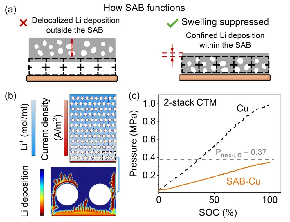
Figure 2. Space-adaptive buffer layer mechanism showing confined lithium deposition and reduced pressure for SAB-Cu versus bare Cu current collector.
A graphical summary comparing the SAB design logic against battery cycling behavior shows that unmodified anode-free cells decay rapidly on cycling, while SAB-modified cells show markedly extended cycle life alongside low swelling, low stress concentration, and low cumulative stress.
5. Multi-Stack Pouch Cell Validation: Cycling, Pressure, and In-Situ X-Ray CT
The study validated pouch cells built with different numbers of stacked layers. Cycling, pressure, and in-situ X-ray CT results showed that a fully charged control cell’s thickness increased by 70 μm, while the SAB-AF-LMB showed almost no thickness change. Even as the stack count increased to 12 layers, the SAB system kept the swelling rate stable at or below 0.02% per cycle. As stack count increased, SAB-modified cells showed only a small decline in the number of cycles reached before falling to 80% capacity retention, while the unmodified control cells declined rapidly.
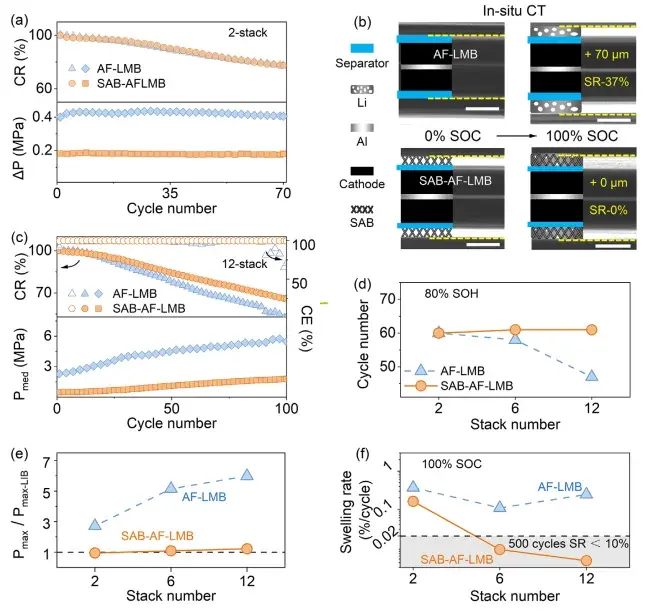
Figure 3. Cycling stability, pressure, and in-situ X-ray CT data for 2-stack and 12-stack AF-LMB versus SAB-AF-LMB pouch cells
6. Mitigating Local Stress Concentration
Beyond controlling overall pressure, relieving local stress concentration is critical to cell safety. Pressure-distribution heat-map results showed a pressure variance of approximately 0.005 MPa² for SAB-AF-LMB, a 6-fold reduction relative to the unmodified control, with the peak local pressure fluctuation reduced from 0.31 MPa to 0.17 MPa. This reduction in local stress concentration helps avoid the risk of dendrite-induced short circuits caused by localized high pressure.
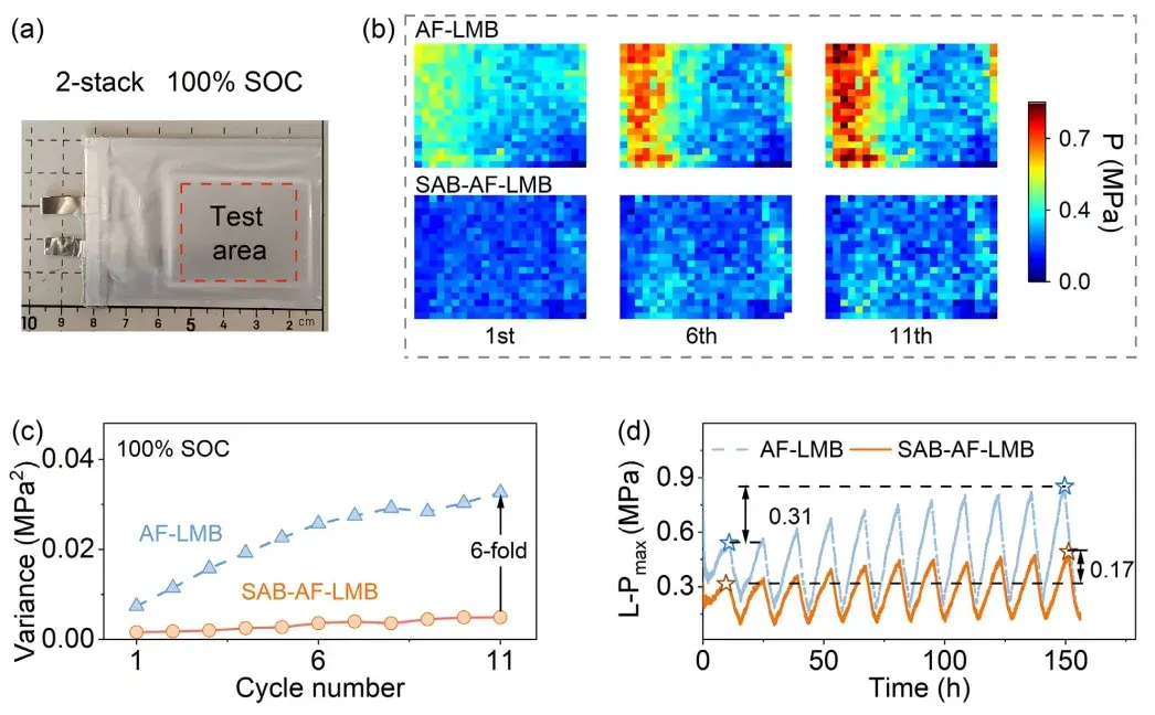
Figure 4. In-situ pressure distribution heat maps showing local stress concentration reduction in SAB-AF-LMB versus AF-LMB pouch cells.
7. Ah-Level Validation: SAB-Cu||NCM9 Pouch Cell (465 Wh/kg)
The team compared an Ah-level SAB-Cu||NCM9 pouch cell against a control AF-LMB (Cu||NCM9) cell without the buffer layer. In a 16-layer, Ah-level SAB-Cu||NCM9 pouch cell, the SAB reduced the local pressure differential from approximately 3 MPa to approximately 1 MPa, and reduced peak local pressure from approximately 8 MPa to approximately 2.4 MPa. This cell achieved a bare-cell gravimetric energy density of 465 Wh/kg and a volumetric energy density of 1330 Wh/L, and avoided the dendrite-puncture failure observed in the control cell under high areal loading and rigid constraint.
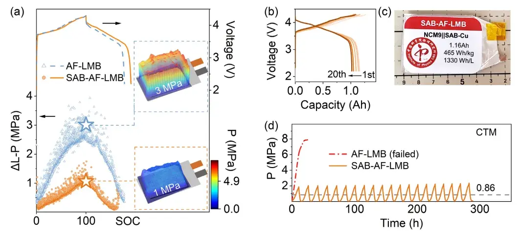
Figure 5. Ah-level SAB-Cu NCM9 pouch cell achieving 465 Wh/kg and 1330 Wh/L energy density with reduced local pressure differential.
8. Ah-Level Validation: Li$_{1.2}$NCM811||SAB-Cu Pouch Cell (418 Wh/kg, 164 Cycles)
A second 1.2 Ah-class Li$_{1.2}$NCM811||SAB-Cu pouch cell reached a bare-cell gravimetric energy density of 418 Wh/kg and a volumetric energy density of 1061 Wh/L. After 164 cycles, capacity retention stood at 77%, with an overall cell swelling rate of only 3.6% and stress accumulation maintained at a low level throughout. By comparison, the unmodified control cell reached an approximately 28% swelling rate within 100 cycles, and its cycle life ended before 100 cycles due to a sharp drop in Coulombic efficiency. This corresponds to the SAB holding the swelling rate to roughly 0.02% per cycle — a level approaching what is acceptable for commercial lithium-ion batteries. Notably, the SAB layer accounted for only about 2% of total cell mass, so adding the buffer structure did not meaningfully sacrifice energy density.
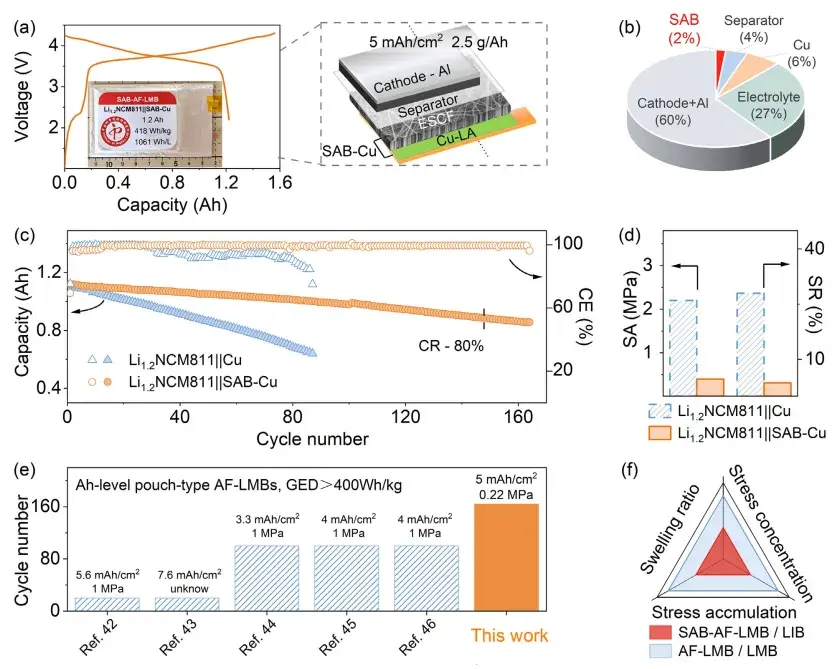
Figure 6. Ah-level Li1.2NCM811 SAB-Cu pouch cell achieving 418 Wh/kg energy density with 77 percent capacity retention after 164 cycles.
10. Measurement Methods: IEST SWE2110 and IEST BER2500
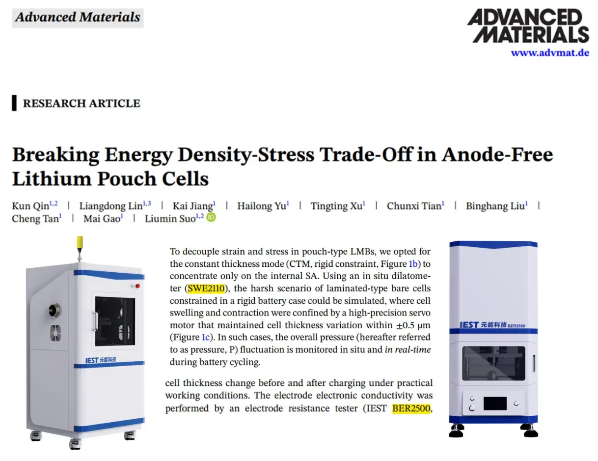
The in-situ mechanical and electrical characterization tools used in this study were an essential experimental foundation for resolving the coupled relationship between stress and swelling and for validating the SAB approach at multiple scales. The IEST SWE2110 in-situ cell swelling tester performed the cell-level mechanical characterization: the 2-, 6-, and 12-layer cell pressure data reported throughout the paper were obtained entirely using this instrument, under both practical working condition (PWC) and constant-thickness mode (CTM) test protocols. The IEST BER2500 electrode resistance tester was used primarily for conductivity verification and rapid screening of SAB scaffold materials during the material design phase.
11. Why This Matters Beyond a Single Metric
This research moves past optimizing any single performance metric in isolation. It demonstrates coordinated optimization across high energy density, low expansion, low stress, multi-layer stacking, and Ah-level cell scale within the same anode-free lithium metal battery design. Achieving that combination required resolving the underlying trade-off between energy density and mechanical stress rather than treating each dimension separately.
12. FAQs
What is an anode-free lithium metal battery (AF-LMB)?
An AF-LMB is a lithium battery built without pre-placed metallic lithium on the negative electrode; lithium plates directly onto the bare current collector during the first charge. This construction supports mass energy densities above 400 Wh/kg and volumetric energy densities above 1000 Wh/L, but is prone to larger cell swelling than conventional lithium-ion batteries.
What is the difference between lithium metal expansion under zero restraint and under constant-thickness mode (CTM)?
Under zero restraint, a cell is free to swell, and AF-LMB and LMB cells reached swelling ratios of 33% and 74% respectively versus 6% for a conventional LIB. Under constant-thickness mode, a rigid casing prevents swelling, so the same deformation converts into internal pressure instead, reaching roughly 1 to 5 MPa across 2- to 12-layer AF-LMB stacks.
How does a space-adaptive buffer (SAB) layer reduce stress in anode-free pouch cells?
The SAB uses a lithium-philic induction layer and a three-dimensional conductive scaffold to confine lithium deposition within its own internal pore volume rather than letting it grow outward. This absorbs cell deformation like a spring, reducing peak pressure toward conventional lithium-ion battery levels and cutting local pressure variance roughly 6-fold in the tested 2-stack cells.
What energy density and swelling rate did the SAB-AF-LMB pouch cells achieve?
A: An Ah-level SAB-Cu||NCM9 pouch cell reached 465 Wh/kg and 1330 Wh/L, and a Li₁.₂NCM811||SAB-Cu pouch cell reached 418 Wh/kg and 1061 Wh/L with 77% capacity retention after 164 cycles and a 3.6% overall swelling rate, corresponding to roughly 0.02% swelling per cycle.
How is in-situ swelling and pressure measured in anode-free lithium metal pouch cells?
In this study, cell thickness and pressure were measured throughout charge/discharge cycling using the IEST SWE2110 in-situ cell swelling tester, under both a practical working condition (free swelling) mode and a constant-thickness mode that simulates a rigid battery casing. Electrode-level conductivity of the buffer scaffold material was separately measured using the IEST BER2500 electrode resistance tester.
