

Sodium ions have a smaller Stokes radius and a lower solvation energy than lithium ions, giving sodium-ion batteries favorable kinetic characteristics for high-power output and low-temperature operation. However, beyond the intrinsic properties of the active materials, the microstructure of the porous electrode has a critical influence on fast-charging capability, cycle life, and low-temperature performance. Systematic electrode-level research that links microstructural behavior to macroscopic cell performance therefore helps clarify the cross-scale evolution mechanisms of the battery system, and provides a key experimental basis for optimizing electrode structure design.
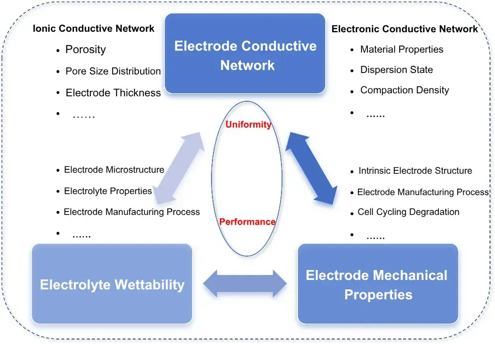
Figure 1. Diagram of porous sodium-ion battery electrode performance factors including ionic and electronic conductive networks, wettability, and mechanical properties
The overall performance of a porous electrode depends heavily on its solid-phase electron-conducting network, which is governed by material properties, compaction density, and component distribution at the microstructural level. In practice, however, electrodes often exhibit structural non-uniformity. Uneven electronic conductivity leads to uneven current distribution, causing excessively vigorous local reactions and substantial Joule heating. At low temperature, intrinsic electron mobility decreases, and any non-uniformity in the conductive network will significantly amplify local current concentration and heat accumulation, accelerating structural degradation and capacity fade in the electrode material. Optimizing the electron-conducting network is therefore practically important for maintaining power output and cycling stability under extreme operating conditions.
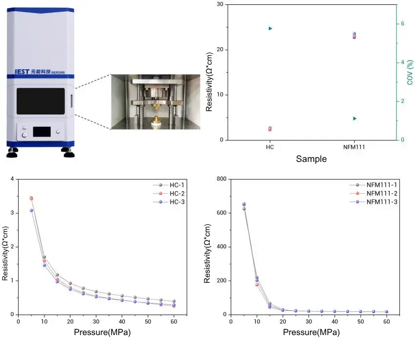
Figure 2. IEST BER2500 electrode resistance tester and resistivity data for hard carbon anode and NFM111 cathode electrodes under varying compaction pressure
The microstructural parameters of a porous electrode directly determine the spatial uniformity of ionic conductivity. Under high-power output, non-uniform ionic conductivity intensifies concentration polarization, limits effective ion transport, and weakens rate capability. At low temperature, electrolyte viscosity increases and intrinsic conductivity decreases, so non-uniformity in ionic conductivity further worsens ion transport within the electrode, significantly constraining the battery’s high-power output and low-temperature capability. Electrode-level ionic conductivity testing therefore relates directly to the evaluation and improvement of a sodium-ion battery’s ion-transport capability under fast-charging and low-temperature conditions.
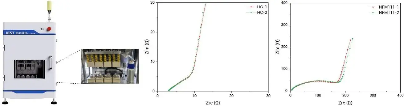
Figure 3. IEST EIC2400M multi-channel ionic conductivity test system with Nyquist plots comparing ionic impedance of hard carbon and NFM111 electrodes
The pursuit of higher energy density continues to drive the development of thick-electrode technology. However, increasing electrode thickness introduces a set of problems: electrolyte wetting becomes more difficult, solid-liquid interfacial contact becomes incomplete, and ion and electron transport paths lengthen, which further intensifies concentration polarization between the separator side and the current-collector side of the electrode. These effects significantly constrain sodium-ion battery performance under high-power output and low-temperature conditions. Systematically characterizing how the electrolyte wets the electrode is therefore essential for optimizing sodium-ion battery performance under these demanding conditions.

Figure 4. Electrolyte wettability test data showing liquid level decline over time for hard carbon and NFM111 sodium-ion battery electrodes
| HC Sample | 50 s Liquid Level Drop (mm) | 60 s Liquid Level Drop (mm) | 100 s Liquid Level Drop (mm) |
|---|---|---|---|
| 1 | 8.966 | 8.779 | 8.088 |
| 2 | 8.969 | 8.799 | 8.161 |
| 3 | 8.875 | 8.723 | 8.132 |
| Mean | 8.936 | 8.767 | 8.127 |
| COV (%) | 0.49 | 0.37 | 0.37 |
| NFM111 | 50 s Liquid Level Drop (mm) | 100 s Liquid Level Drop (mm) | 150 s Liquid Level Drop (mm) |
|---|---|---|---|
| 1 | 9.289 | 8.609 | 7.923 |
| 2 | 9.229 | 8.504 | 7.772 |
| 3 | 9.509 | 8.966 | 8.39 |
| Mean | 9.342 | 8.693 | 8.028 |
| COV (%) | 1.29 | 2.27 | 3.28 |
In high-power and low-temperature scenarios, rapid, repeated expansion and contraction of the active material, combined with low-temperature brittle fracture of the electrode, can weaken electrode mechanical stability and readily trigger active-material shedding and cell failure. Good mechanical flexibility is therefore an important precondition for maintaining structural stability, preserving intact ion and electron transport pathways, and achieving reliable operation under extreme operating conditions.
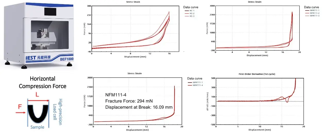
Figure 5. IEST BEF1000 electrode flexibility tester and force-displacement curves for hard carbon and NFM111 electrode bending fracture tests
The deformation behavior of multi-layer electrode compression is jointly influenced by the intrinsic properties of the material and the electrode’s microstructure. The resulting stress-strain curve can be used to guide electrode formulation design and compaction process optimization. Because this analysis can simulate the actual stacked state of a laminated cell, it can effectively evaluate electrode mechanical stability, providing a mechanical basis for improving high-power output, low-temperature performance, and cycle life in sodium-ion batteries.
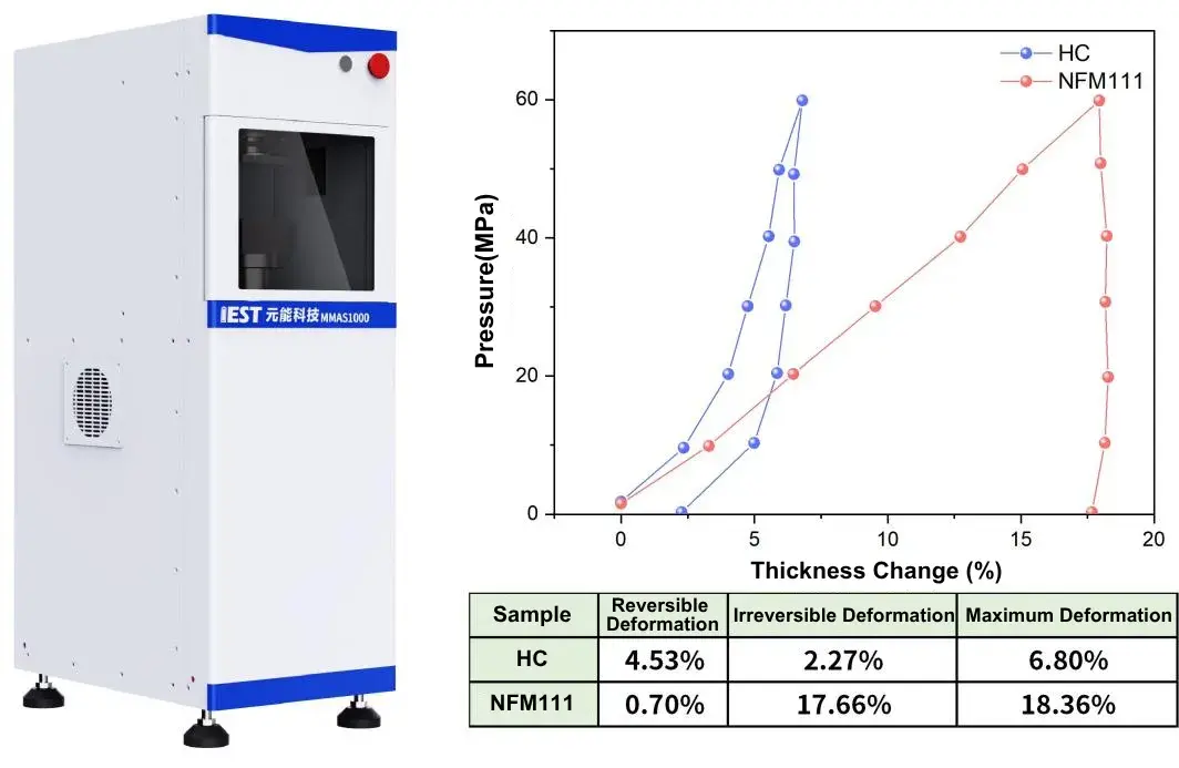
Figure 6. IEST MMAS1000 multi-level mechanical property analysis system and compression stress-strain data for hard carbon and NFM111 multi-layer electrodes
| TESTING MATRIX | WHAT IT MEASURES | INSTRUMENT USED | RELEVANCE TO POWER / LOW-TEMPERATURE PERFORMANCE |
|---|---|---|---|
| Electron conductivity | Electrode resistivity vs. compaction pressure | IEST BER2500 electrode resistance tester | Uneven electron conduction concentrates current and heat, worsening at low temperature |
| Ionic conductivity | Ionic impedance uniformity (Nyquist plots) | IEST EIC2400M multi-channel ionic conductivity test system | Non-uniform ionic conductivity intensifies concentration polarization under fast charge and cold conditions |
| Electrolyte wettability | Liquid-level decline over time, mean and COV | IEST Electrode Electrolyte Wetting Tester | Poor wetting limits solid-liquid contact, worsening as electrode thickness increases |
| Electrode flexibility | Force and displacement at coating fracture | IEST BEF1000 electrode flexibility tester | Low flexibility risks active-material shedding under repeated expansion/contraction and cold brittleness |
| Multi-layer compression | Reversible / irreversible / maximum deformation | IEST MMAS1000 multi-level mechanical property analysis system | Excessive irreversible deformation compromises stacked-cell mechanical stability over cycling |
| PROPERTY | HARD CARBON (HC) ANODE | NFM111 LAYERED OXIDE CATHODE | IMPLICATION FOR ELECTRODE / CELL DESIGN |
|---|---|---|---|
| Resistivity at 25 MPa | ≈ 2.5 Ω·cm (COV ≈ 5.5%) |
≈ 23 Ω·cm (COV ≈ 1%) |
NFM111 shows higher absolute resistivity but better batch-to-batch consistency at this pressure |
| Ionic impedance scale (Nyquist) | 0–30 Ω | 0–400 Ω | HC anode shows substantially lower ionic transport resistance than the NFM111 cathode |
| Wetting COV at longest time point | 0.37% (100 s) | 3.28% (150 s) | HC shows more consistent electrolyte wetting across replicate samples |
| Flexibility fracture behavior | Not fractured within tested range | Fractured at 294 mN, 16.09 mm displacement | NFM111 cathode is more prone to bending-induced fracture than the HC anode |
| Compression deformation (reversible / irreversible / max) |
4.53% / 2.27% / 6.80% | 0.70% / 17.66% / 18.36% | NFM111 shows far greater irreversible deformation under multi-layer compression, a mechanical stability concern for stacked cells |
Taken together, these five characterization methods connect electrode microstructure to macroscopic cell behavior. Electron and ionic conductivity data reveal how uniformly current and ions are transported through the electrode; wettability data show how thoroughly the electrolyte penetrates the porous structure; and flexibility and multi-layer compression data reveal how mechanically robust the electrode is under the expansion, contraction, and stacking stresses encountered in a real cell. NFM111 showing both a bending fracture event and substantial irreversible compression deformation, compared with HC, points to mechanical stability as a distinct engineering consideration for this cathode material in stacked-cell formats.
This research moves beyond single-metric evaluation of active materials and instead evaluates the porous electrode as a system. Combining electron conductivity, ionic conductivity, electrolyte wettability, electrode flexibility, and multi-layer compression data provides a practical basis for electrode formulation design, process window definition, and thick-electrode development, in support of improved high-power output and low-temperature performance in sodium-ion batteries.
[1] Okoshi, M., Yamada, Y., Komaba, S., et al. “Theoretical Analysis of Interactions between Potassium Ions and Organic Electrolyte Solvents: A Comparison with Lithium, Sodium, and Magnesium Ions.” Journal of The Electrochemical Society, 2016, 164(2): A54–A60.
[2] Meng, D., Ma, Z., Li, L. “Mesoscale reaction heterogeneities in lithium-ion batteries“. Chemical Industry and Engineering Progress, 2021, 40(9): 4869–4881.
[3] Wang, C., Zhang, A., Chang, Z., et al. “Progress in structure design and preparation of porous electrodes for lithium ion batteries.“Journal of Materials Engineering, 2022, 50(1): 67–79.
[4] Ma, Q., Kong, L.-Y., Guo, B.-Y., et al. “Layered Oxide Cathodes for Sodium-Ion Batteries: Origins of Microcracks and Countermeasures.” Chemical Science, 2026, 17(21): 10329–10354.
Electrode characterization is the measurement of a coated electrode’s physical properties — including electronic conductivity, ionic conductivity, electrolyte wettability, electrode flexibility, and compression behavior — to understand how its microstructure affects cell-level power output, low-temperature performance, and cycle life.
In the data presented here, the hard carbon (HC) anode showed lower resistivity and lower ionic impedance than the NFM111 layered oxide cathode, along with more consistent electrolyte wetting. The NFM111 cathode showed a bending fracture event and substantially higher irreversible compression deformation, indicating different mechanical and transport behavior between the two electrode types.
Electrode resistivity is tested by measuring resistance under a range of applied compaction pressures, then converting to resistivity using the sample’s geometry. In the data referenced here, this was performed using the IEST BER2500 electrode resistance tester across a pressure range of 5 MPa to 60 MPa.
In the wettability data presented here, the HC anode maintained a coefficient of variation (COV) at or below 0.49% across the tested time points, while the NFM111 cathode’s COV rose to 3.28% at 150 seconds. A rising COV over time indicates less consistent wetting behavior across replicate samples, which is a relevant consideration as electrode thickness increases.
Multi-layer compression testing measures how much an electrode stack deforms reversibly versus irreversibly under pressure, simulating conditions inside a stacked cell. In the data shown here, the NFM111 cathode’s irreversible deformation (17.66%) was far higher than that of the HC anode (2.27%), which is a relevant factor in electrode mechanical stability over repeated cycling.
