-
iestinstrument
IEST Facilitates Lithium-ion Battery Failure Analysis
1. Preface
Lithium-ion batteries are a relatively complex chemical system. With the breakthroughs in lithium-ion battery materials and manufacturing processes in recent years, lithium batteries are widely used in new energy vehicles and large power station energy storage fields. As the market gradually develops, lithium-ion batteries are used in more and more scenarios, and there are more and more failure modes. How to quantitatively analyze lithium-ion battery failure and thereby improve the battery cell design and manufacturing process is undoubtedly a very important part of the research and development and design process. The failure analysis of lithium-ion batteries is a relatively large subject, involving multiple levels and including system, structure, process, materials and other factors.
Lithium-ion battery failure is mainly divided into two types: one is performance failure, and the other is safety failure. Performance failure includes many aspects such as capacity attenuation, capacity diving, abnormal rate performance, abnormal high and low temperature performance, and poor cell consistency. Safety failure refers to the failure of lithium batteries that has certain safety risks due to improper use or abuse, mainly including thermal runaway, gas, leakage, lithium precipitation, short circuit, expansion and deformation, etc. These failures can be decomposed into the following diagram [1]:
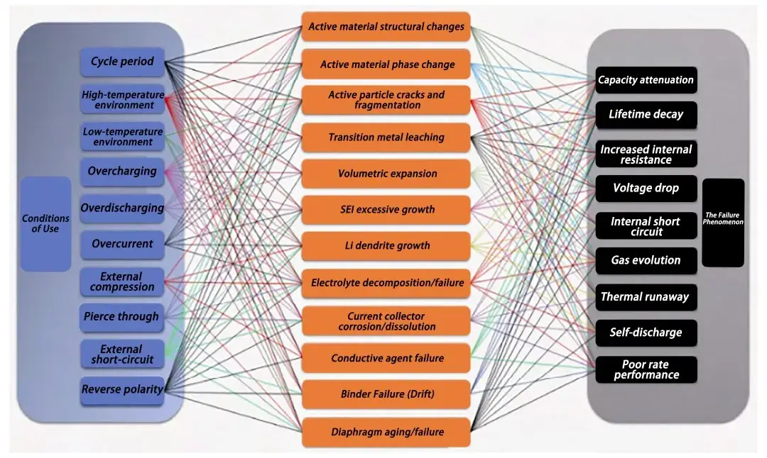
Figure 1. Relationship between lithium-ion battery use conditions, failure mechanisms and failure phenomena
As shown in Figure 2 [2], on the basis of the integrated and integrated system sub-platform of lithium-ion battery failure characterization-battery disassembly sample preparation/transfer/characterization, it is necessary to design a suitable lithium-ion failure analysis scheme for the specific failure phenomenon, and select the above mentioned suitable analysis and testing techniques for the material, electrode, and cell layers respectively, in order to efficiently and accurately obtain the cause of the lithium-ion battery failure. At the same time, it is also necessary to apply advanced testing and characterization and simulation techniques to the lithium-ion failure analysis, especially in-situ characterization and joint characterization techniques and devices. Advanced in-situ characterization techniques can help to deeply understand the reaction mechanism, structural evolution and interface evolution of the battery under the actual use conditions, and avoid the damage to the actual state of the battery after disassembling and testing.
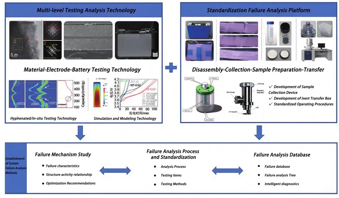
Figure 2. System failure analysis method[2]
Detection is at the heart of lithium-ion battery failure analysis. IEST is a testing instrument supplier rooted in the field of lithium-ion battery testing, and also hopes to contribute its own efforts in the field of lithium-ion battery failure analysis. To this end, we have briefly sorted out the relevant failure analysis processes and made some related applications in conjunction with IEST own instruments.
The lithium-ion battery failure analysis process mainly consists of the following steps:
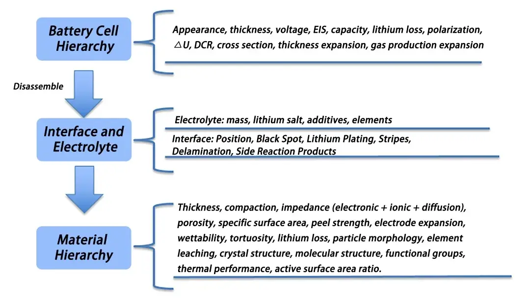 Figure 3. Illustration of the failure analysis process
2. Battery Cell Hierarchy
Before disassembling a battery, we usually conduct some non-destructive analysis on the failed battery. The main steps are as follows:
- Adjust the SOC (100% SOC is suitable for the analysis interface, 0% SOC is suitable for later material analysis), take photos to record the appearance of the battery core, focus on recording the damage, leakage, deformation, gas production, etc. of the battery core, and measure the quality and thickness of the battery core, voltage, etc.
- Remaining capacity, DCR and EIS tests. Place the battery under a certain ambient temperature, charge and discharge from 0% to 100% SOC at a certain rate and detect the remaining capacity of the battery cell at a certain rate. For example, place the battery core in a normal temperature environment of 25°C, charge and discharge at 0.33C or 1C, and detect the remaining capacity CEOL after the battery core fails. After adjusting to a certain SOC, other related tests can be performed. After completing the relevant tests, conduct full-battery DCR and EIS tests to analyze changes in battery cell internal resistance before and after failure.
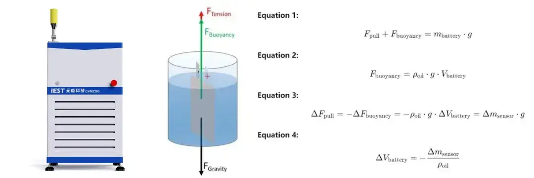
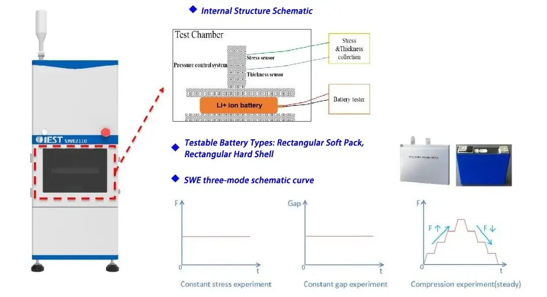
- For battery core thickness or volume expansion/shrinkage testing, IEST in-situ swelling tester and in-situ gas production volume tester are used to simultaneously study the thickness changes and volume changes of the battery core during the charging and discharging process after failure, as shown in Figure 4.
Figure 4. IEST GVM series in-situ gas production volume test system and principle
Figure 5. IEST in-situ SWE series swelling testing system and principle
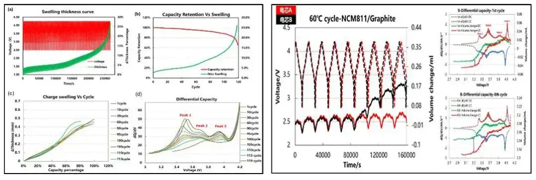
Figure 6. Application Case: Cyclic swelling and gas production in batteries
- Differential capacity testing. Use low rate (usually 00.4C) high frequency sampling point (1s) for charging and discharging. The charge and discharge curves are then made into differential capacity and differential voltage curves, namely dQ/dV and dV/dQ curves. Combining steps 2 and 3, related changes such as cell polarization and loss of active material can be analyzed through the peak shift position and peak intensity of the curve [3].
- Tomographic Analysis. After completing the above related tests, tomography can be performed on the battery core to obtain relevant internal structure information such as dislocation, deformation, and diaphragm shrinkage after aging.
3. Interface and Electrolyte Analysis
After completing all data collection and analysis at the first battery cell level, start dismantling the battery cells. The disassembled battery cells are generally divided into several states: 100% SOC/50% SOC and 0% SOC. 100% SOC/50% SOC cells can be used to observe obvious interface changes and impedance changes, and 0% SOC cells can be used to conduct various material performance tests. The main procedures are as follows:
- Use a special air bag to collect the gas from the battery cells after gas production. After collection, conduct GC test to analyze the gas components. Understanding the gas production, gas components and content during the battery’s full life cycle is important for revealing the battery’s interface reaction mechanism, improving battery safety and cycle life is of great significance.
- Disassemble the 0% SOC cell. After disassembly, the complete JR can be centrifuged using the electrolyte shake-off instrument developed by IEST (Figure 7), to quickly and easily obtain the electrolyte in the gap between the pole pieces (the instrument supports centrifugation of 280Ah large batteries),IC, GC-MS, ICP and other tests are then carried out to analyze the electrolyte consumption and element content. At the same time, take photos to record the interface conditions of the pole pieces, and retain the pole pieces for material level analysis.
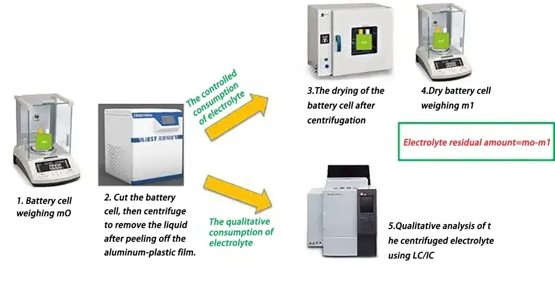 Figure 7. Electrolyte centrifugation test consumption process
- Disassemble the 100% SOC or 50% SOC battery. Use cameras and micrometers to record the interface and thickness of the pole piece, including the interface, position, black spots, lithium precipitation, stripes, stripping and side reactant interface and thickness. During this process, we should focus on whether lithium is precipitated on the surface of the pole piece, the peeling strength of the pole piece, whether there are powder, metal impurities, burrs and other foreign matter on the pole piece, etc.
The characterization of lithium evolution requires not only considering the critical point at which the failure mode is triggered during battery use and monitoring of its evolution process, but also focusing on the multi-level correlation study of the amount of lithium evolution, the location/morphology of lithium deposition and the overall safety of the battery. The peeling strength of the pole piece is one of the important indicators for evaluating the mechanical stability of the pole piece. Common manifestations of the decrease in the peeling strength of the pole piece include the peeling of the coating from the base material, cracking, and partial shedding of the coating, the causative factors are generally divided into repeated swelling and contraction of active materials deintercalating lithium, failure of the binder due to heating of the pole piece, and surface corrosion of the base material. Foreign matter may directly pierce the separator, or it may dissolve in the electrolyte during the battery cycle and precipitate on the surface of the negative electrode to form metal dendrites that pierce the separator, causing a micro short circuit inside the battery and self-discharge.
4. Material Hierarchy Analysis
After all data collection for the electrolyte and interface is completed, material level analysis begins. At this time, different test items can be analyzed using different SOC pole pieces. Different testing items require different pre-treatments. Some materials that are greatly affected by the electrolyte need to be soaked and cleaned in DMC before other tests are performed. The main analysis processes at the material level are as follows:
When the battery core is disassembled to 100% SOC, some interface and material performance analysis is carried out:
- Symmetric cell impedance analysis and tortuosity analysis. Symmetrical battery EIS can analyze the ohmic impedance in the pole piece impedance, the membrane void structure impedance, the ion transport impedance and the diffusion impedance, etc. Analyze and decompose the main sources of battery impedance to analyze the material impedance changes during the failure process and analyze the sources of resistance changes. In this process, the IEST multi-channel ion conductivity tester can be used to quickly assemble and test symmetrical batteries, and at the same time, the pole piece tortuosity test can be performed.
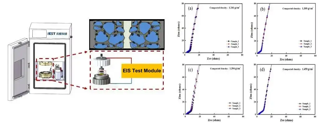 Figure 8. Nyquist diagram of the IEST multi-channel ion conductivity testing system and symmetrical cells with different roll-pressed cathode electrode
- Electrode Resistance Testing. The IEST BER series electrode resistance meter can be used to quickly test the pole piece electronic resistance and analyze the source of growth in battery assembly. Due to the high-precision thickness sensor and pressure sensor, the pressure and resistance changes of the pole piece can be tested in real time. The application case is shown in Figure 10. The black line is the Rs value of the pole piece symmetrical battery, and the blue line is the pole piece resistance Re value. The growth rules of Rs and Re are consistent, but the sources of resistance growth of the two are different during high temperature cycling and high temperature storage, showing that their failure modes are different.
 Figure 9. Principle of Electrode Resistance Testing and BER Series Instruments
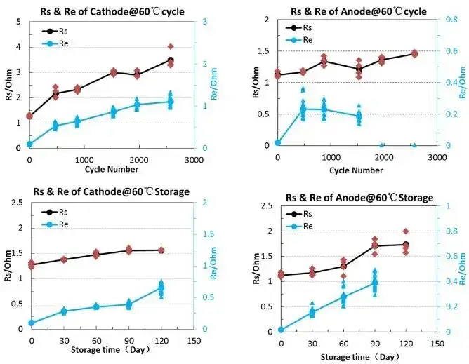 Figure 10. Rs and Re changes during high temperature cycling and high temperature storage
- Material thermal stability analysis. The powder is scraped from the fully charged positive and negative electrode plates, and TG-DSC can be used to analyze the thermal stability of the material and compare the thermal stability changes of the material before and after failure, especially the positive electrode material.
When the battery core is disassembled and reaches 0% SOC, the physical and chemical properties of the material are analyzed:
- Capacity analysis. Wipe one side of the pole piece and assemble it into a reverse buckle, and perform a gram capacity test to analyze the remaining capacity and reversible capacity of the material. Comparing the dQ/dV curve of the full battery can conduct a more complete analysis of lithium loss and polarization loss [4].
- Active surface area. The CV test method can be used to analyze the material activity specific surface, so as to conduct a side analysis of the material side reactions.
- Porosity test. Porosity testing can be performed using mercury intrusion method or true density method. Since mercury is a highly toxic substance, the industry currently mainly uses the true density method to test the porosity of pole pieces.
- Material morphology and surface element analysis. CP-SEM-EDS can be used to observe the morphology of the pole pieces and materials, including expansion, agglomeration, fragmentation, side reaction accumulation and related morphological changes. At the same time, combined with EDS, you can view the changes in surface elements of the material and analyze the generation of side reactants. For example, if the silicon negative electrode expands greatly and the expansion thickness is different when prepared by different processes, the actual expansion will be different between the RSS expansion test and the CP-SEM test, as shown in Figure 12.
![]() Figure 11. Coulombic Swelling Testing System and Silicon Anode Swelling Rapid Screening System
Figure 11. Coulombic Swelling Testing System and Silicon Anode Swelling Rapid Screening System
![]() Figure 12. Swelling Variations of Different Silicon Materials and Actual Electrode Thickness Testing
Figure 12. Swelling Variations of Different Silicon Materials and Actual Electrode Thickness Testing
- Analysis of crystal structure and molecular structure. Using instruments such as XPS, NMR, CZE, Raman, XRD, TEM, TUNA, FITR, and Raman, the crystal structure and surface molecular structure changes before and after material failure can be fully analyzed. Combined with impedance analysis, failure source analysis can be better performed. Thereby focusing on improving lithium-ion battery failure [4].
- Element analysis. Using ICP to perform elemental analysis on the positive and negative electrode plates, separators and electrolytes can determine the changes in material elements. In particular, targeted analysis of partially coated elements and easily precipitated elements can quickly determine material coating failure and element dissolution phenomena, make targeted improvements.
5. Summary
As one of the products of multi-disciplinary cross-fusion, lithium-ion batteries play an important role in existing social production and life and will play an increasingly important role in future life. For lithium-ion battery failure analysis and detection, more and more methods have been developed, and people have a deeper understanding of the battery mechanism. As a young member rooted in the testing industry, IEST hopes to use new testing technology to help industry personnel have a deeper understanding of materials and cells, optimize material design and process design, and improve product consistency and reliability, make a small contribution to failure analysis technology.
6. References
[1] Wang Qiyu, Wang Shuo, et al., Overview of Lithium-ion Battery Failure Analysis, Energy Storage Science and Technology, 2017, Vol5, No.15
[2] Wang Yi, Chen Xuebing, Wang Yuanxi, et al. Review of multi-level failure mechanism and analysis technology of energy storage lithium-ion batteries [J]. Energy Storage Science and Technology, 2023, 12(7):2079-2094.
[3] Dr. Kun, Li Xiang Life Public Account: Lithium-ion Battery Disassembly Failure Analysis Method, 2023-06-22
[4] Fang Chenxu, Research on the performance failure mechanism of long-term energy storage batteries, New Material Application and Characterization Technology (Xiamen) Exchange Conference, 2023
[5] Wei Liying, Failure Analysis of Key Materials in Li-ion Batteries, New Material Application and Characterization Technology (Xiamen) Exchange Conference, 2023
Subscribe Us
Contact Us
If you are interested in our products and want to know more details, please leave a message here, we will reply you as soon as we can.


