

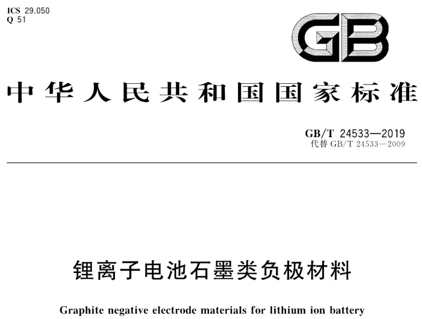
Accurate measurement of powder compaction density and powder conductivity is critical in lithium-ion battery material characterization. Relevant Chinese national standards — GB/T 24533-2019 (“Graphite anode materials for lithium-ion batteries”) for anode powder testing, and GBT 30835-2014 (“Carbon composite lithium iron phosphate cathode materials for lithium-ion batteries”) for LFP density evaluation — outline specific testing protocols. Notably, the two standards differ in whether properties are measured under applied pressure or after its release, which can lead to meaningful variation in reported values if the measurement state is not explicitly specified.
For graphite anode materials, GB/T 24533-2019 specifies measuring compaction density after pressure release: the powder is compressed, held under pressure for 30 seconds, and the thickness is measured after unloading using a vernier caliper. This “unloading” method accounts for the thickness rebound, or spring-back, that occurs post-compression. Conversely, for LFP cathode materials, conductivity can be measured via two primary methods: Electrochemical Impedance Spectroscopy (EIS) and the Four-Point Probe Method. The EIS method typically measures the impedance of a pellet after it has been pressed and removed from the die (an unloading-mode measurement), whereas the Four-Point Probe Method often measures resistance while the powder remains under a specified applied pressure (a loading-mode, or pressed-state, measurement). Comparing material properties across sources therefore requires careful attention to the testing conditions and parameters used.
This article presents a comparative analysis of powder compaction density and powder conductivity for both graphite and LFP materials, examining the differences between measurements taken during the loading and unloading cycles.
 |
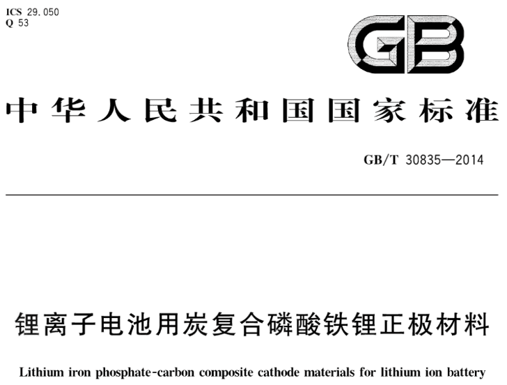 |
Figure 1. Chinese national standards GB/T 24533-2019 (graphite anode) and GBT 30835-2014 (LFP cathode) governing powder compaction density and powder conductivity testing
The tests were performed using the PRCD1100 powder resistivity and compaction density tester (IEST), shown in Figure 2. As a piece of battery powder compaction tooling, this instrument is designed for synchronized measurement of density and resistance during both pressurization and depressurization, eliminating the need for separate loading-state and unloading-state test setups.
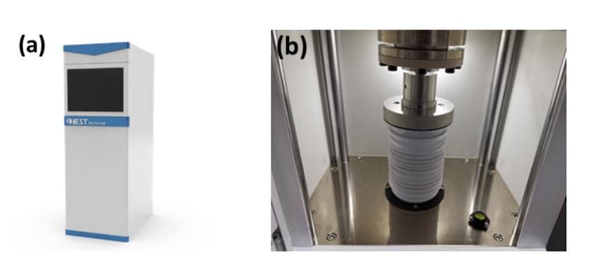
Figure 2. (a) Appearance and (b) structure of the IEST PRCD1100 battery powder compaction tooling, used for synchronized powder compaction density and powder conductivity testing
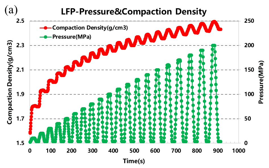
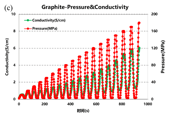
The experiments employed the four-point probe method. The applied pressure range was 10–200 MPa, in increments of 10 MPa. Pressure was held for 10 seconds at each step during loading. Subsequently, pressure was reduced to 3 MPa and held for 10 seconds during the unloading phase.
A precise mass of 1.0000 ± 0.0010 g was used for both graphite and LFP powders.
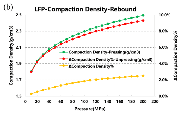
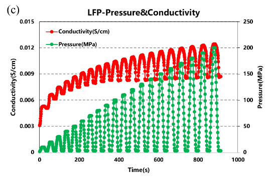
As shown in Figure 3, the powder compaction density and powder conductivity of LFP powder change with applied pressure during both loading and unloading cycles. Notably, at approximately 200 MPa, the difference in compaction density between the loading and unloading states is about 3%. However, the difference in powder conductivity is much more significant, reaching approximately 30%.
 |
 |
 |
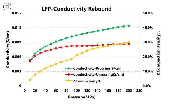 |
Figure 3. LFP powder compaction density and powder conductivity measurement during loading and unloading — IEST PRCD1100, four-point probe method
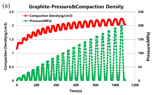
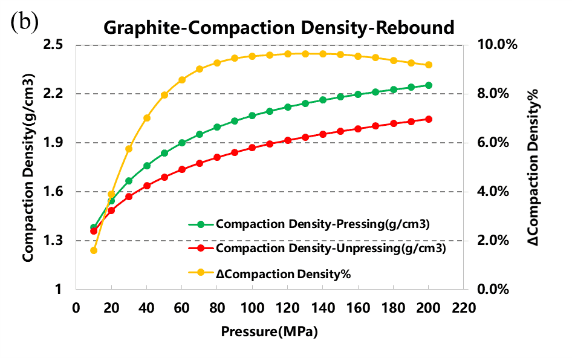
Figure 4 illustrates the behavior of graphite powder in this anode powder testing sequence. The divergence between loading and unloading curves for both density and conductivity is more pronounced than for LFP. At nearly 200 MPa, the compaction density difference between cycles is about 10%, while the conductivity difference is substantially larger, at approximately 80%.
 |
 |
 |
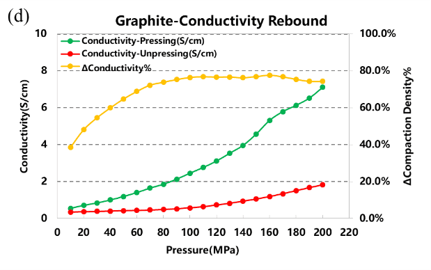 |
Figure 4. Curves showing the variation in graphite powder compaction density and conductivity during loading and unloading
| Property | LFP Powder (Cathode) | Graphite Powder (Anode) | Implication for Testing Protocol |
|---|---|---|---|
| Compaction density difference (~200 MPa) | ~3% | ~10% | Graphite shows greater elastic rebound after unloading than LFP |
| Powder conductivity difference (~200 MPa) | ~30% | ~80% | Conductivity is far more sensitive to measurement state than density for both materials |
| Relevant standard | GBT 30835-2014 | GB/T 24533-2019 | Standards specify unloading-state measurement; loading-state (pressed-state) data must be reported separately if used |
| Common conductivity method | EIS (unloading) or four-point probe (loading) | Four-point probe (loading, as tested here) | Method choice determines whether loading- or unloading-state values are obtained |
The experimental data demonstrate two central points:
Powder compaction density depends on measurement state. Unloaded density values incorporate elastic rebound and therefore understate the instantaneous packing that a cell experiences during calendering or in a compressed electrode stack.
Powder conductivity is strongly pressure-dependent. Powder conductivity measured under load (four-point probe) reflects improved particle-particle and particle-probe contact and reduced pore resistance. The unloaded EIS/pellet measurement captures post-relaxation conductivity and will be lower in many cases — sometimes dramatically, as with graphite anode powder testing (≈80% lower near 200 MPa).
These effects arise because compression closes interparticle gaps, increases real contact area, and can cause deformation that creates metallic or graphitic contact bridges. Upon unloading, elastic recovery reintroduces gaps and reduces the number of percolation paths.
Our results demonstrate that testing conditions profoundly impact the measured values of lithium battery powder properties. The choice between loading and unloading modes significantly influences the outcome. At a pressure close to 200 MPa:
For LFP materials, the difference in compaction density is ~3%, while the difference in powder conductivity is ~30%.
For graphite anode powder testing, the difference is more substantial, with compaction density varying by ~10% and powder conductivity by ~80%.
Therefore, explicitly stating the measurement mode (loading vs. unloading) is essential for accurate material comparison and quality control.
PRCD Series Powder Compaction Density & Resistance Tester (IEST): synchronous compaction density and resistance testing for lithium battery powders in both pressurized and discharged states, supporting two-probe and four-probe methods across three primary test modes:
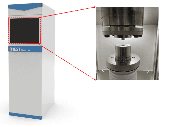
Figure 5. IEST PRCD Series battery powder compaction tooling — synchronized compaction density and powder conductivity testing in pressurized and depressurized states
[2] GB/T 24533-2019《 Lithium-Ion Battery Graphite Negative Pole Material”》
Pressed-state (loading) density is measured while the powder remains under applied pressure, while unloaded (relaxed-state) density is measured after pressure release and includes elastic rebound. At ~200 MPa, this difference is about 3% for LFP powder and about 10% for graphite anode powder.
Powder conductivity measurement commonly uses either the four-point probe method, which records resistance while the powder is under applied pressure (loading state), or Electrochemical Impedance Spectroscopy (EIS) on a pressed and removed pellet (unloading state). The two methods can yield substantially different values for the same material.
Selecting battery powder compaction tooling depends on whether both pressed-state and unloaded-state data are needed within a single test cycle, and whether two-probe or four-probe resistance measurement is required. The IEST PRCD1100 addresses these requirements by synchronizing compaction density and resistance measurement throughout both pressurization and depressurization.
In this study, graphite anode powder testing showed an approximate 80% difference in powder conductivity between loading and unloading states near 200 MPa, compared with approximately 30% for LFP cathode powder. Values of this magnitude indicate that reported conductivity data must specify the measurement state to be meaningful.
GB/T 24533-2019 (graphite anode materials) specifies compaction density measurement after pressure release, accounting for thickness rebound, while conductivity methods referenced for GBT 30835-2014 (LFP cathode materials) include both loading-state (four-point probe) and unloading-state (EIS) approaches. Reporting the applicable standard alongside the measurement state avoids ambiguity in cross-material comparison.
Relevant characterization tests for battery electrode powders include powder compaction density (under pressure and after unloading), powder conductivity via four-point probe or EIS, particle size distribution, and tap density. For lithium-ion cathode and anode powders specifically, synchronized compaction density and conductivity testing across a pressure range (e.g., 10–200 MPa) is commonly used to characterize both loading- and unloading-state behavior.
