

With the rapid development of the lithium battery industry, lithium-ion batteries have been widely used in mobile phones, computers, automobiles, energy storage, and other fields. Users have higher and higher requirements for fast charging, and the corresponding requirements for battery rate performance are also increasing. Rate performance is closely related to battery resistance, which includes ionic resistance and electronic resistance. Because the electronic portion can be evaluated before slurry mixing and coating, accurate powder resistance measurement offers a fast route to pre-screen materials for cathode powder battery testing and to predict finished electrode resistance, accelerating formulation choices and process optimization.
In the full battery electronic resistance, positive electrode resistance usually accounts for a relatively large share. Positive electrode sheet resistance is affected by a variety of materials, including active materials, adhesives, and conductive carbon; the active material content ratio is as high as 95% or more. When the ratio of other materials is fixed, powder resistance and electrode sheet resistance are theoretically expected to show a certain degree of correlation. If this correlation can be determined, evaluation of cell resistance can be advanced from the electrode end to the material end — saving R&D and production costs while accelerating R&D progress.
There are currently two methods for testing cathode active material powder resistance: the four-probe method and the two-probe method. The four-probe method characterizes the lateral resistance of the surface of the powder tablet, while the two-probe method tests the longitudinal resistance of the powder tablet. Electrode resistance is usually tested using the two-probe method; for details, see “New method for monitoring stability and uniformity of battery electrode.”
In order to ensure the comparability of the test results, the four-wire method based on the two-probe method and the double-disc electrode with controllable pressure were selected for the powder resistance and electrode resistance tests. The powder resistance tester reached a maximum applied pressure of 200 MPa, making the compacted state of the powder closer to the compacted state of the powder in the electrode.
Model PRCD1100 (IEST), electrode diameter 16mm, test pressure range 10~200MPa, holding time 10s. The equipment is shown in Figure 1(a) and 1(b).
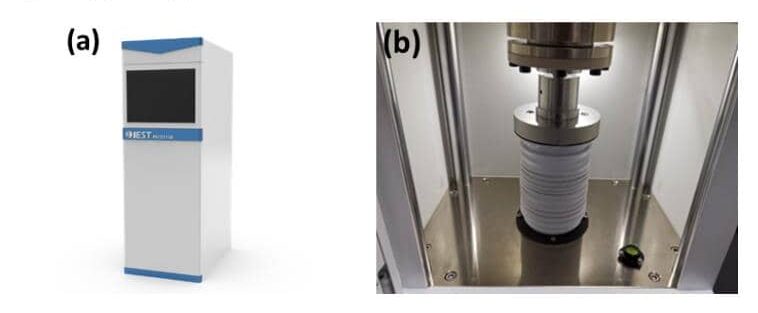
Figure 1. (a) PRCD1100 appearance; (b) PRCD1100 structure — used for cathode active material powder resistance testing
Model BER1300 (IEST), electrode diameter 14mm, applied pressure 25MPa, holding time 25s. The equipment is shown in Figure 2(a) and 2(b).
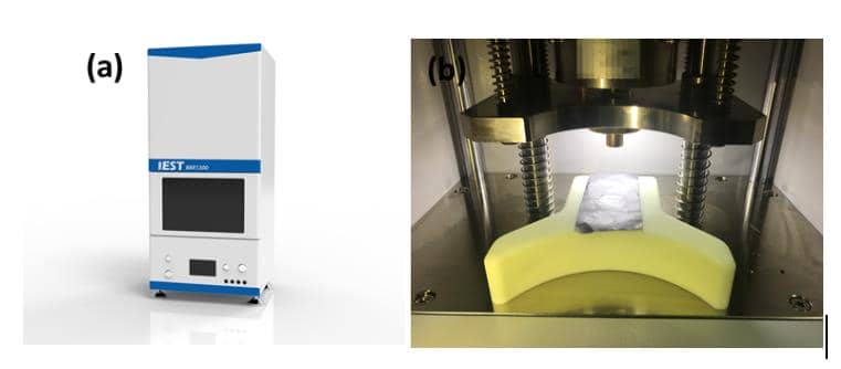
Take 1~2g of powder sample, weigh it and pour it into the fixture (PR-Device-16), pre-vibrate the powder on the pre-vibration instrument (Pre-V1) to make the accumulation state of the powder consistent before pressing. Put the fixture into the powder resistance meter PRCD1100, start the PRCDMS software to set the test pressure and pressure holding time parameters, and the software automatically reads the data of powder sample thickness, compacted density, resistance, resistivity, conductivity and other data.
Cut the rolled electrode into a rectangular size of about 5cm × 10cm, place it between the two electrodes of the electrode resistance meter, start the MRMS software, and set parameters such as test pressure, holding time, and active substance quality. The software automatically reads electrode thickness, compacted density, resistance, resistivity, conductivity, and other data.
Lithium cobalt oxide material is currently the most widely used cathode material for consumer batteries. Due to its large powder resistance and poor conductivity, LCO material often needs to be modified, such as by doping or coating. Figure 3(a) shows the powder resistance test of LCO material before and after modification, with the relationship curve between powder conductivity and powder compaction density automatically obtained.
From the figure, at compaction density less than 3.87 g/cm³ (pressure applied at 75 MPa), the conductivity of the modified powder is lower than before modification; when compaction density is greater than 3.87 g/cm³, the conductivity of the modified powder begins to exceed that of the unmodified powder, and increases rapidly with further compaction density increase. Comparing Figure 3(b), the conductivity of electrodes (electrode compaction density 4.0 g/cm³) prepared from the two powders with the same formula and process shows that the modified LCO electrode conductivity is significantly better than before modification — confirming the modification was effective. These results show that for this material, when the pressure state of the powder is consistent with the pressure state of the powder in the electrode, powder resistance and electrode resistance show a consistent trend.
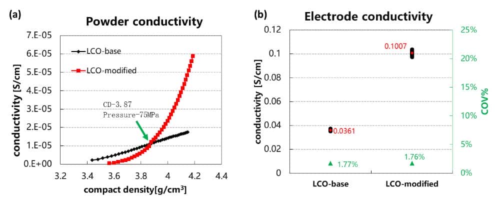
Figure 3. (a) Powder conductivity vs. compaction density for LCO before/after modification; (b) corresponding electrode conductivity — confirming powder resistance and electrode resistance track together
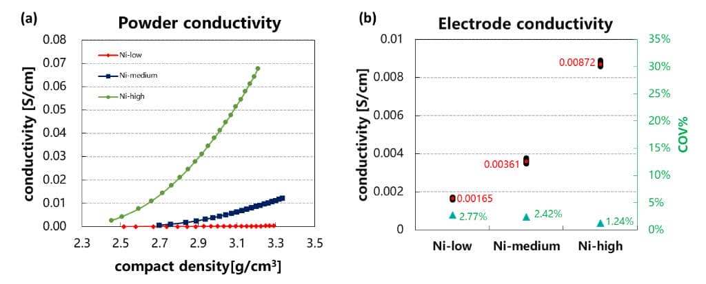
Nickel-cobalt-manganese ternary materials are the first choice of cathode materials for most power batteries due to their higher gram capacity. Gram capacity is mainly affected by Ni content — the higher the Ni content, the higher the reversible capacity, but increasing Ni content also affects cycling, rate, and thermal stability to a certain degree. Figure 4(a) shows the relationship between powder conductivity and powder compaction density for three different Ni content levels. As Ni content increases, powder conductivity also shows an increasing trend. Comparing electrode conductivity (electrode compaction density 3.2 g/cm³) prepared with the same formula and process in Figure 4(b), the same trend of electrode conductivity increasing with Ni content is observed. These results indicate that ternary powder resistance and electrode resistance have a corresponding relationship.
With the market’s strong requirements for power battery safety, lithium iron phosphate materials are gradually becoming the preferred cathode material for many power battery companies due to their high structural stability. However, LFP material itself has poor conductivity and needs to be modified in advance before use in power batteries requiring high rate performance. Common modification methods are doping, carbon coating, and nano-sizing. Figure 5(a) compares powder conductivity and compaction density of LFP materials with three different modification methods. Under the same compaction density conditions, the conductivity trend of the three materials is: LFP-1 > LFP-2 > LFP-3. Comparing electrode conductivity (electrode compaction density 2.4 g/cm³) prepared with the same formula and process, the same trend — LFP-1 > LFP-2 > LFP-3 — is observed, so powder conductivity can be used to quickly evaluate the effect of modification.
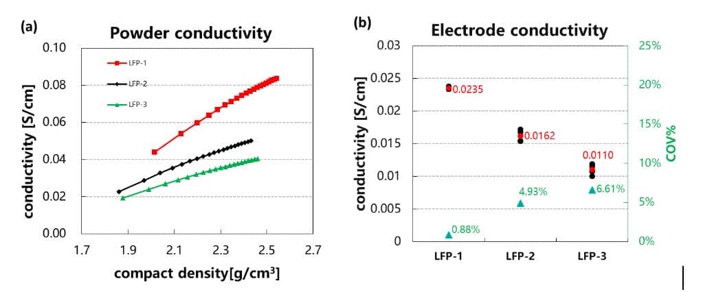
Figure 5 (a) Comparison of the relationship between the conductivity of the LFP powder before and after modification and the compacted density; (b) Comparison of the conductivity of the electrode prepared by the LFP material before and after modification
| Cathode System | Variable Studied | Electrode Compaction Density | Powder-Electrode Correlation |
|---|---|---|---|
| LCO | Before vs. after modification (doping/coating) | 4.0 g/cm3 | Modified powder conductivity exceeds unmodified above 3.87 g/cm3 powder compaction density; electrode conductivity shows the same reversal |
| NCM | Three different Ni content levels | 3.2 g/cm3 | Powder conductivity increases with Ni content; electrode conductivity shows the same increasing trend |
| LFP | Three modification methods (LFP-1/2/3) | 2.4 g/cm3 | Powder conductivity ranking LFP-1 > LFP-2 > LFP-3 matches electrode conductivity ranking exactly |
Moving Cathode Powder Battery Testing Earlier in the Development Workflow
Across all three cathode systems, powder resistance and electrode resistance track together once the powder compaction state is matched to the electrode’s actual compaction state. This means cathode powder battery testing performed early — before slurry mixing and coating — can substitute for a full electrode-fabrication cycle when pre-screening a material modification or formulation change, provided the applied pressure is chosen to replicate the electrode’s compaction density. The IEST PRCD1100 supports the pressure range (up to 200 MPa) needed to reach this matched state for powder testing, while the IEST BER1300 validates the corresponding electrode-level resistance and conductivity.
The IEST PRCD1100 measures powder resistance and compaction density up to 200 MPa; the IEST BER1300 measures the corresponding electrode resistance and compaction density — together supporting cathode powder battery testing that predicts electrode-level performance earlier in development.
In this paper, the four-probe method and the controllable-voltage double-disc electrode method were used to test the powder resistance and electrode resistance of lithium cobalt oxide, ternary, and lithium iron phosphate materials, with compaction density obtained simultaneously for both. When the compacted state of the powder is close to the compressed state of the powder in the electrode, powder resistance shows the same trend as electrode resistance across all three systems, so evaluation of the cell’s electronic resistance can be advanced from the electrode end to the powder end. Integrating this powder resistance screening into the development workflow enables faster material selection and optimization, significantly reducing costs and time-to-market for new battery designs.
[1] B.G. Westphal et al. Influence of high intensive dry mixing and calendering on relative electrode resistivity determined via an advanced two point approach. Journal of Energy Storage 2017, 11, 76–85
[2] Hiroki Kondo et al. Influence of the Active Material on the Electronic Conductivity of the Positive Electrode in Lithium-Ion Batteries. Journal of The Electrochemical Society, 2019,166 (8) A1285-A1290
[3] Nils Mainusch et al. New Contact Probe and Method to Measure Electrical Resistances in Battery Electrodes Energy Technol. 2016, 4, 1550-1557
[4] Xu Jieru, Li Hong, et al., Conductivity measurement and analysis methods in lithium battery research Energy storage science and technology,2018,7(5) 926-955.
[5] Nie Lei, Qin Xing, Zhang Na, etc Research on pre-evaluation method of lithium ion battery resistance, power supply technology,2019, 43(4): 562-563;
[6] Zhuang Quanchao, Xu Shoudong, Qiu Xiangyun, etc Electrochemical impedance spectroscopy analysis of lithium ion batteries Chemical progress,2010,22(6):1044-1057;
[7] Yu Chenjie et al. Progress in Synthesis and Modification of LiFePO4 Cathode Material for Lithium Ion Rechargeable Batteries,2011,29(3): 468-470;
Cathode powder battery testing measures a cathode active material powder’s resistance and compaction density under controlled applied pressure. Because the electronic resistance contribution can be evaluated before slurry mixing and coating, testing the powder directly allows R&D teams to pre-screen material modifications and predict finished electrode resistance earlier, without needing to fabricate a full electrode first.
Yes, when the powder’s applied compaction pressure is chosen to match the compaction state the powder experiences inside the finished electrode. Across LCO, NCM, and LFP cathode systems, powder conductivity trends (with modification, Ni content, or formulation changes) matched the corresponding electrode conductivity trends in every case tested.
Ionic resistance covers lithium-ion transport through the electrolyte in electrode pores, through the SEI layer, and solid-phase diffusion within the active material. Electronic resistance covers the active material powder’s own resistance, current collector resistance, and contact resistances between components — the portion this study’s powder resistance testing directly addresses.
The four-probe method characterizes the lateral resistance across the surface of a powder tablet, while the two-probe method tests the longitudinal (through-thickness) resistance of the powder tablet. Electrode resistance testing is usually performed with the two-probe method, since it better represents the through-thickness current path in an actual electrode.
Powder conductivity generally increases with compaction density, but the relationship can be non-monotonic when comparing modified versus unmodified materials — as seen with LCO, where modified powder conductivity was lower than unmodified below 3.87 g/cm³ but higher above it. Matching the test pressure to the electrode’s actual compaction density is therefore essential for a meaningful comparison.
